Manufacturing method of display device

Active Publication Date: 2016-07-28
TCL CHINA STAR OPTOELECTRONICS TECH CO LTD
View PDF4 Cites 0 Cited by
  • Summary
  • Abstract
  • Description
  • Claims
  • Application Information

AI Technical Summary

Benefits of technology

[0009]Aspects of embodiments of the present invention are directed to a method of manufacturing a display device includ

Problems solved by technology

The LCD device has an issue of inferior si

Method used


Image

  • Manufacturing method of display device
  • Manufacturing method of display device
  • Manufacturing method of display device

Examples


Embodiment Construction

[0035]Advantages and features of the present invention and methods for achieving them will be made clear from embodiments described below in detail with reference to the accompanying drawings. The present invention may, however, be embodied in many different forms and should not be construed as being limited to the embodiments set forth herein. Rather, these embodiments are provided so that this disclosure will be thorough and complete, and will fully convey the scope of the invention to those skilled in the art. The present invention is merely defined by the scope of the claims. Therefore, well-known constituent elements, operations and techniques are not described in detail in the embodiments in order to prevent the present invention from being obscurely interpreted. Like reference numerals refer to like elements throughout the specification.

[0036]The spatially related terms “below”, “beneath”, “lower”, “above”, “upper”, and the like, may be used herein for ease of description to ...


PUM


Abstract

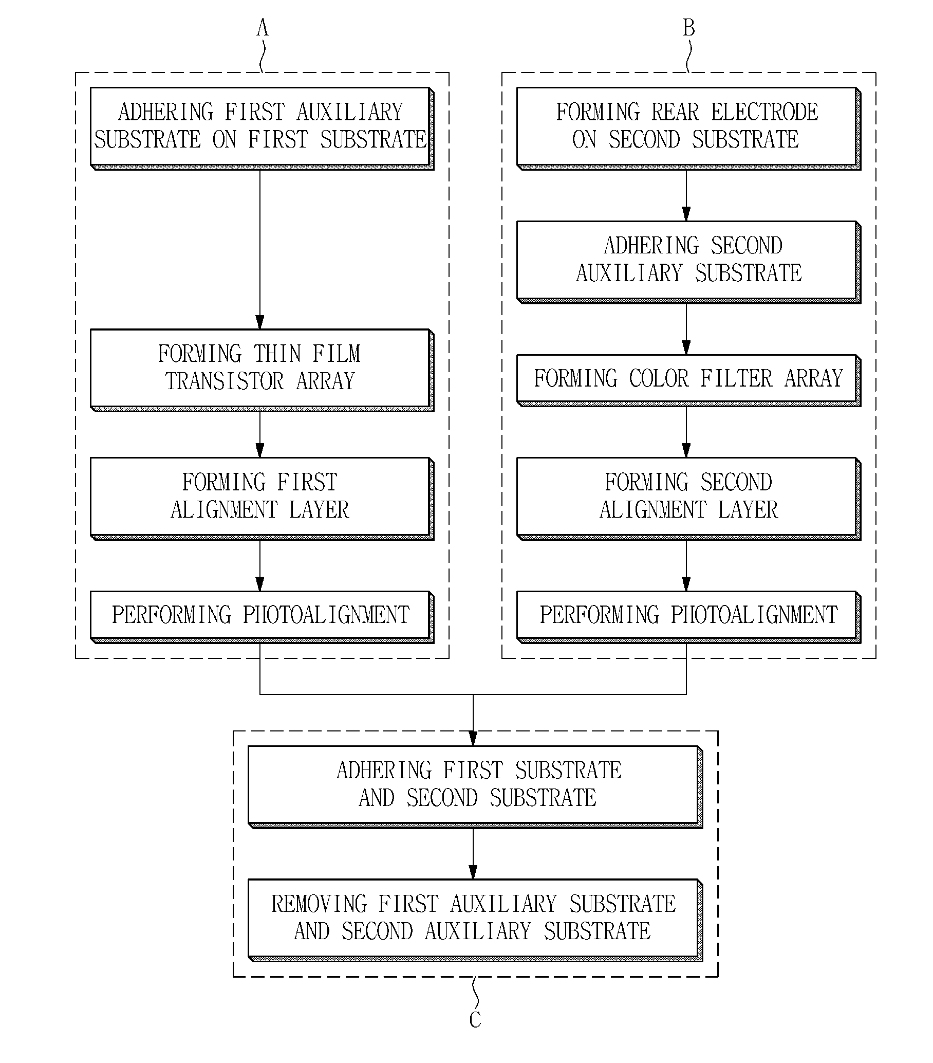
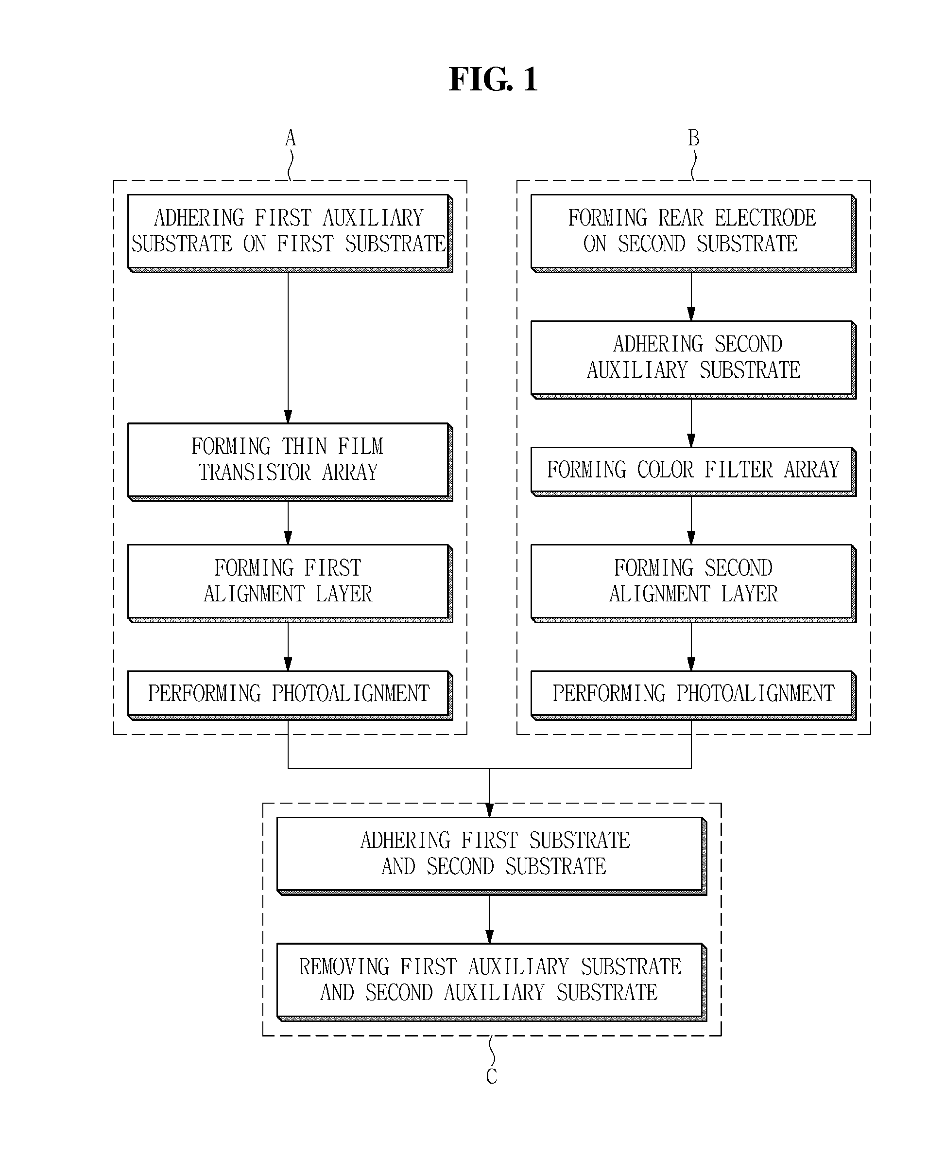
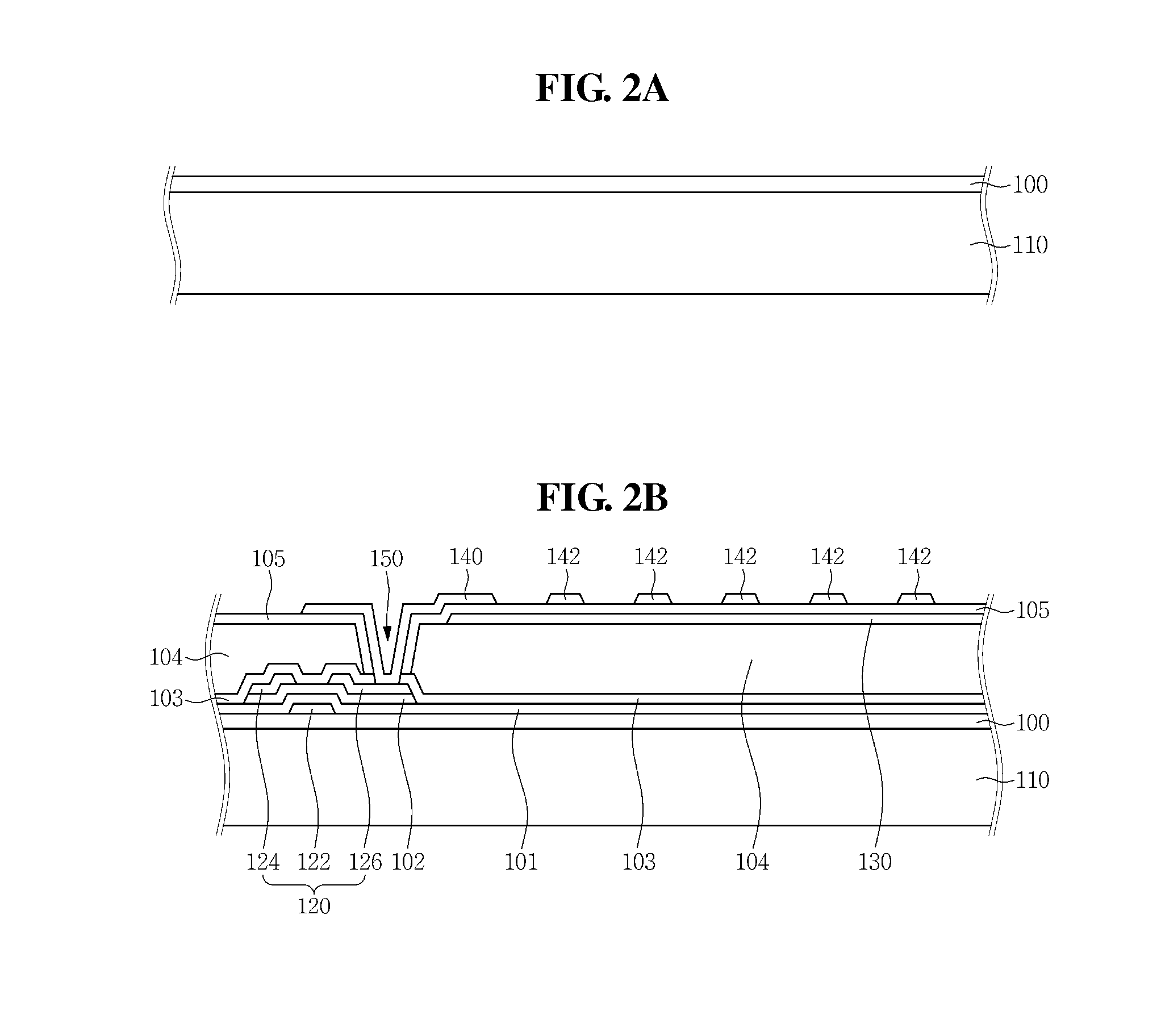
A method of manufacturing a display device including a thin substrate disposed with a rear electrode that is capable of preventing defects caused by static electricity, the method comprising adhering a first auxiliary substrate on an outer surface of a first substrate; forming a rear electrode on an outer surface of a second substrate, the second substrate being disposed opposed to the first substrate; adhering a second auxiliary substrate on the rear electrode; disposing a liquid crystal layer between an inner surface of the first substrate and an inner surface of the second substrate and adhering the first substrate and the second substrate together; and removing the first auxiliary substrate and the second auxiliary substrate from the first substrate and the second substrate, respectively.

Description

CLAIM OF PRIORITY[0001]This application claims the priority of and all the benefits accruing under 35 U.S.C. §119 of Korean Patent Application No. 10-2015-0010705, filed on Jan. 22, 2015, with the Korean Intellectual Property Office (KIPO), the disclosure of which is incorporated herein in its entirety by reference.BACKGROUND OF THE INVENTION[0002]1. Field of Disclosure[0003]Embodiments of the present invention relate to a method of manufacturing a display device.[0004]2. Description of the Related Art[0005]A liquid crystal display (LCD) device is a type of flat panel displays (FPDs), which is most widely used these days. An LCD device includes two substrates including electrodes formed thereon and a liquid crystal layer interposed therebetween. Upon applying voltage to two electrodes, liquid crystal molecules of the liquid crystal layer are rearranged, thereby adjusting an amount of transmitted light.[0006]The LCD device has an issue of inferior side visibility relative to front vi...

Claims


Application Information

Patent Timeline
IPC IPC(8): G02F1/1343H01L27/12G02F1/1337G02F1/1335G02F1/1339G02F1/136
CPCG02F1/13439G02F1/1339G02F1/136G02F2001/133357G02F1/133516H01L27/1225G02F1/133788G02F1/1333G02F1/1341H01L27/1266G02F1/133354G02F1/1343G02F2202/22H01L27/14634H01L27/1469G02F1/133357
Inventor KIM, YOUNGGUPARK, KYUNGHOPARK, SUJIPARK, YEONGRONGJEON, BAEKKYUNJUNG, MINSIKHUR, JAEWEON
Owner TCL CHINA STAR OPTOELECTRONICS TECH CO LTD
Why Eureka
Try Eureka