Image forming system

a technology of image forming and forming tubes, applied in the field of image forming systems, can solve problems such as the degradation of the quality of the output image obtained, and achieve the effect of preventing image defects

Inactive Publication Date: 2012-11-15
CANON KK
View PDF3 Cites 9 Cited by
  • Summary
  • Abstract
  • Description
  • Claims
  • Application Information

AI Technical Summary

Benefits of technology

[0009]The present invention has an object to prevent, in an image forming system, in particular, a multiply-connecting image forming system capable of subjecting a recording material having an image formed thereon by a first image forming apparatus to image formation by a second image forming apparatus, degradation in quality of an output image in a case where the first image forming apparatus has run out of toner during duplex image formation and in a case where only the second image forming apparatus continues image formation.
[0021]According to the image forming system of the present invention, in the case where the image forming apparatus on the upstream side has run out of toner during duplex image formation and only the image forming apparatus on the downstream side continues the duplex image formation in the multiply-connecting image forming system, the image defect can be prevented through the application of an appropriate transfer voltage.

Problems solved by technology

Therefore, the image forming apparatus on the downstream side needs to be set in an appropriate transfer condition, which may otherwise lead to degradation in quality of an output image obtained through the image formation on the downstream side.

Method used


Image

  • Image forming system
  • Image forming system
  • Image forming system

Examples


first embodiment

[0110]FIG. 9 is a flowchart illustrating control for automatic changeover to the second duplex image forming mode according to a first embodiment of the present invention. FIG. 10 is an explanatory graph showing a relationship between the number of passages through the fixing device and the amount of water contained in the recording material. FIG. 11 is an explanatory graph showing settings on the recording material sharing voltage to be performed in accordance with the type of the recording material. FIG. 12 is an explanatory graph showing settings on the recording material sharing voltage to be performed in accordance with the absolute amount of water in the surrounding environment.

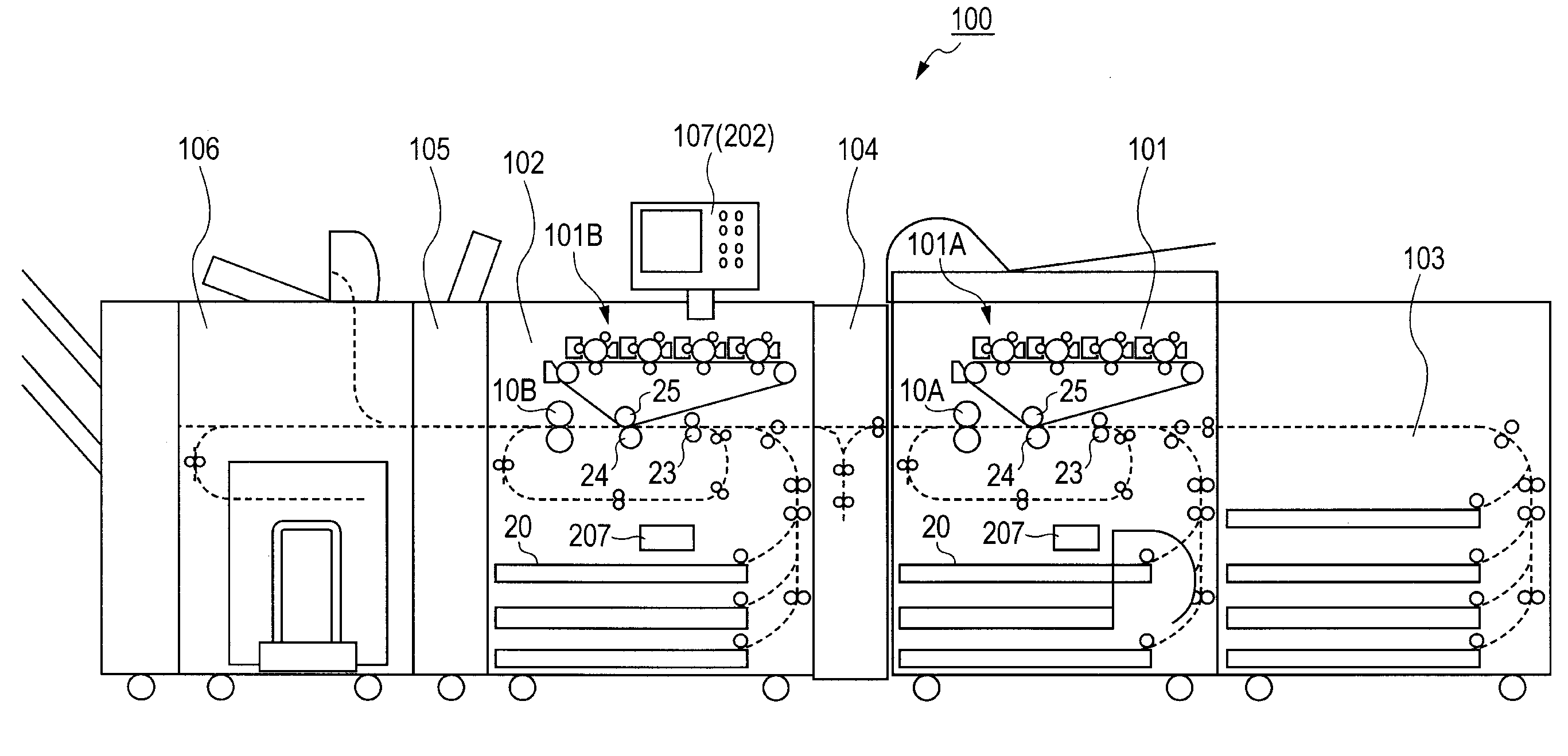
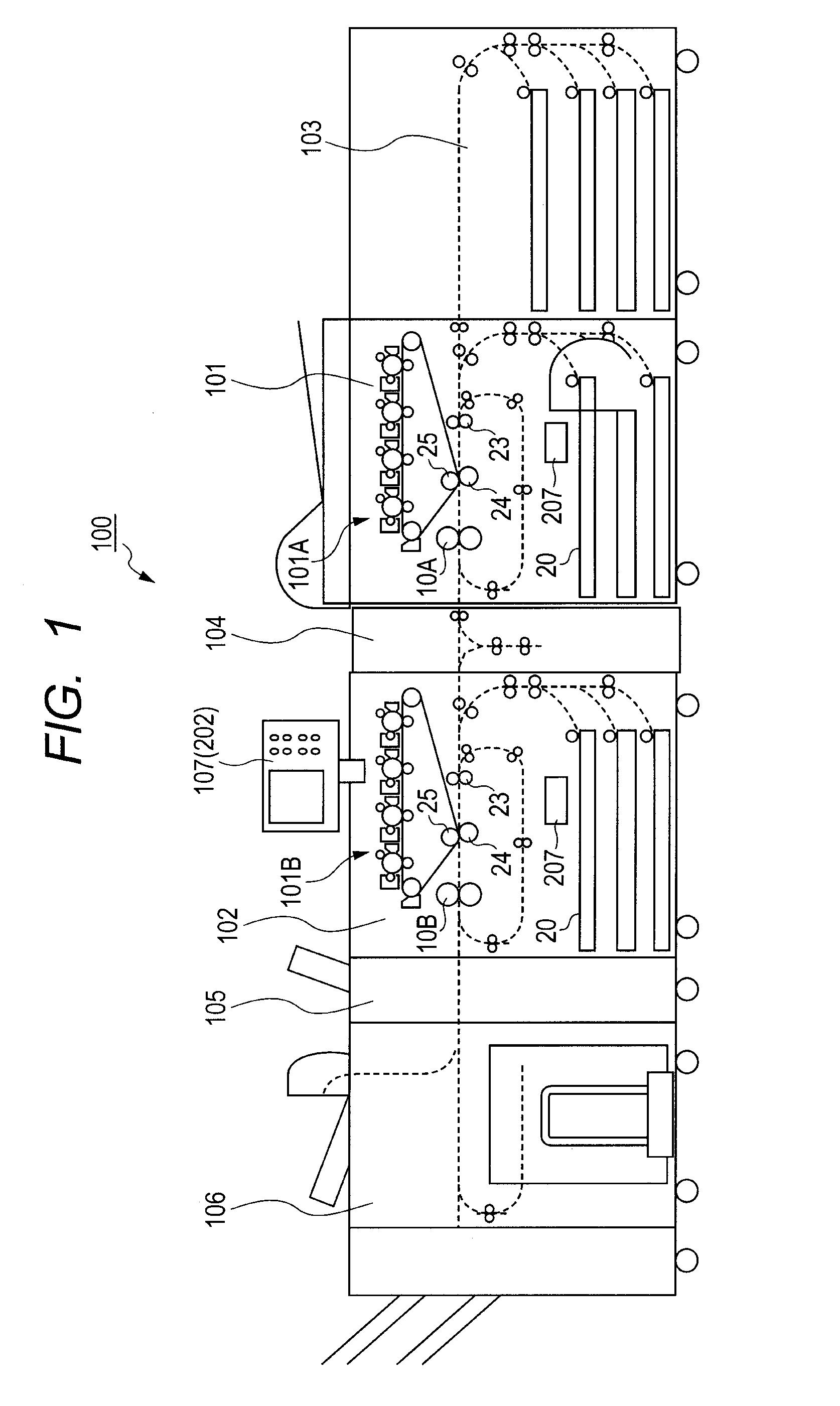
[0111]As illustrated in FIG. 1, when abnormality occurs in the toner image forming portion 101A in a period in which an image is formed by the second image forming apparatus 102 on the recording material having an image formed thereon by the first image forming apparatus 101, a determining unit of the c...

second embodiment

[0135]FIG. 13 is a flowchart illustrating control for automatic changeover to the second duplex image forming mode according to a second embodiment of the present invention. FIG. 14 is an explanatory graph showing a relationship between the temperature of the fixing roller and the amount of reduction in amount of water contained in the recording material.

[0136]In the first embodiment, the description is directed to the control to be performed in the state in which the fixing device 10A of the first image forming apparatus 101 is controlled at the specified temperature. The temperature of the fixing roller of the first image forming apparatus 101 is controlled at the specified temperature, and hence the amount of water contained in the recording material that is heated when passing through the fixing device 10A exhibits a constant value. However, when the first image forming apparatus 101 transitions to a power saving mode, the temperature state of the fixing device 10A varies. Under...


PUM


Abstract

A multiply-connecting image forming system in which a second image forming apparatus forms an image on a recording material on which an image has been formed by a first image forming apparatus, the multiply-connecting image forming system suppressing degradation in quality of an output image when only the second image forming apparatus continues duplex image formation because the first image forming apparatus has run out of toner during the duplex image formation.

Description

BACKGROUND OF THE INVENTION[0001]1. Field of the Invention[0002]The present invention relates to an image forming system, and more particularly, to an image transfer control, in a multiply-connecting image forming system capable of subjecting a recording material having an image formed thereon by a first image forming apparatus to image formation by a second image forming apparatus, for the second image forming apparatus in a case where only the second image forming apparatus continues image formation.[0003]2. Description of the Related Art[0004]There is widely used an image forming apparatus in which a toner image forming portion forms a toner image and transfers the toner image onto a recording material, and then a fixing portion heats and pressurizes the recording material to fix the image onto the recording material. Further, there is widely used an image forming apparatus capable of performing duplex printing, including a reverse conveyance mechanism configured so that the reco...

Claims


Application Information

Patent Timeline
Patent Type & Authority Applications(United States)
IPC IPC(8): G03G15/22
CPCG03G15/238G03G15/2078G03G15/2039G03G2215/00021
Inventor HANO, MASAMINAKAYAMA, TOSHINORI
Owner CANON KK
Why Eureka
Try Eureka