System for screen dance studio
- Summary
- Abstract
- Description
- Claims
- Application Information
AI Technical Summary
Benefits of technology
Problems solved by technology
Method used
Image
Examples
first embodiment
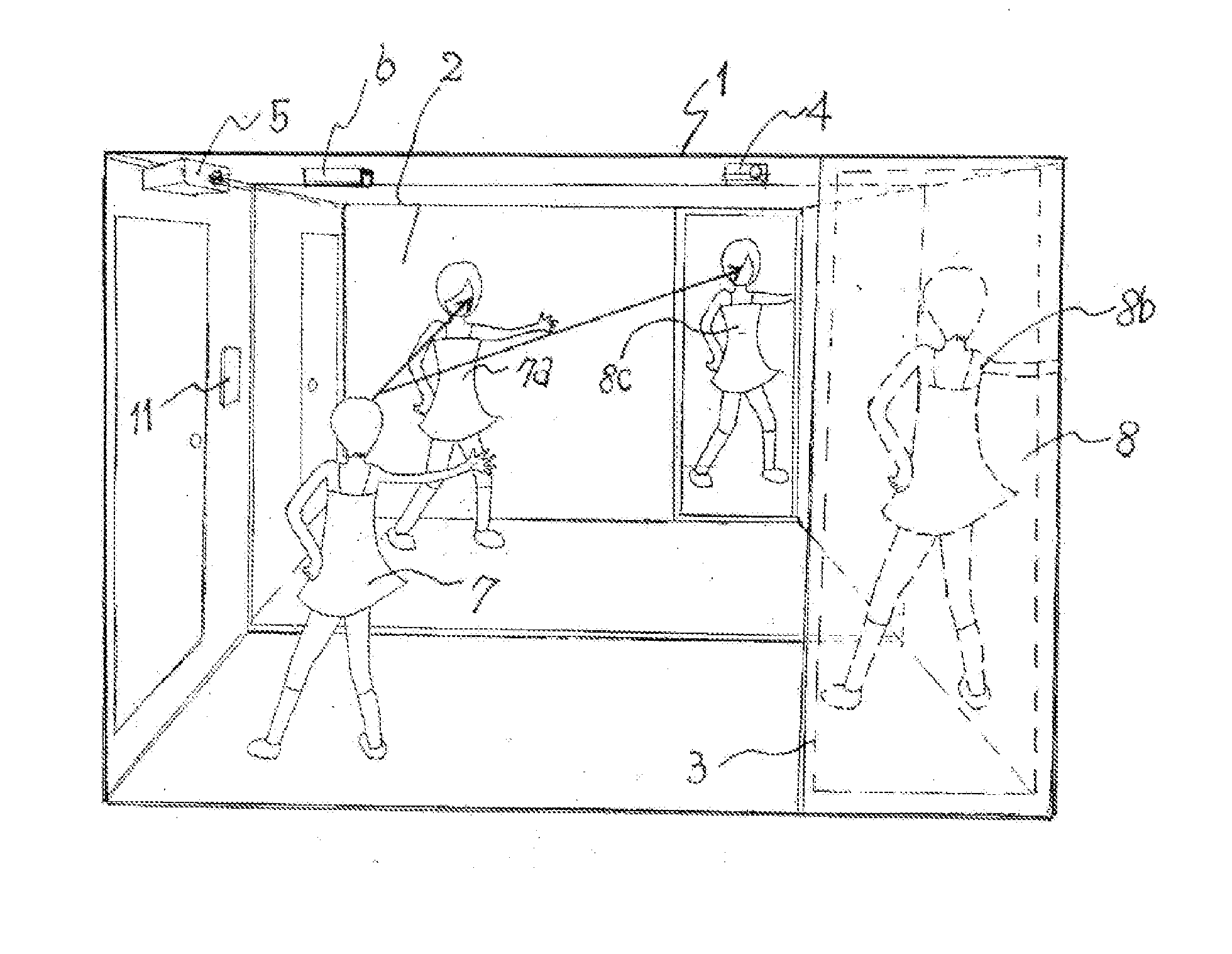
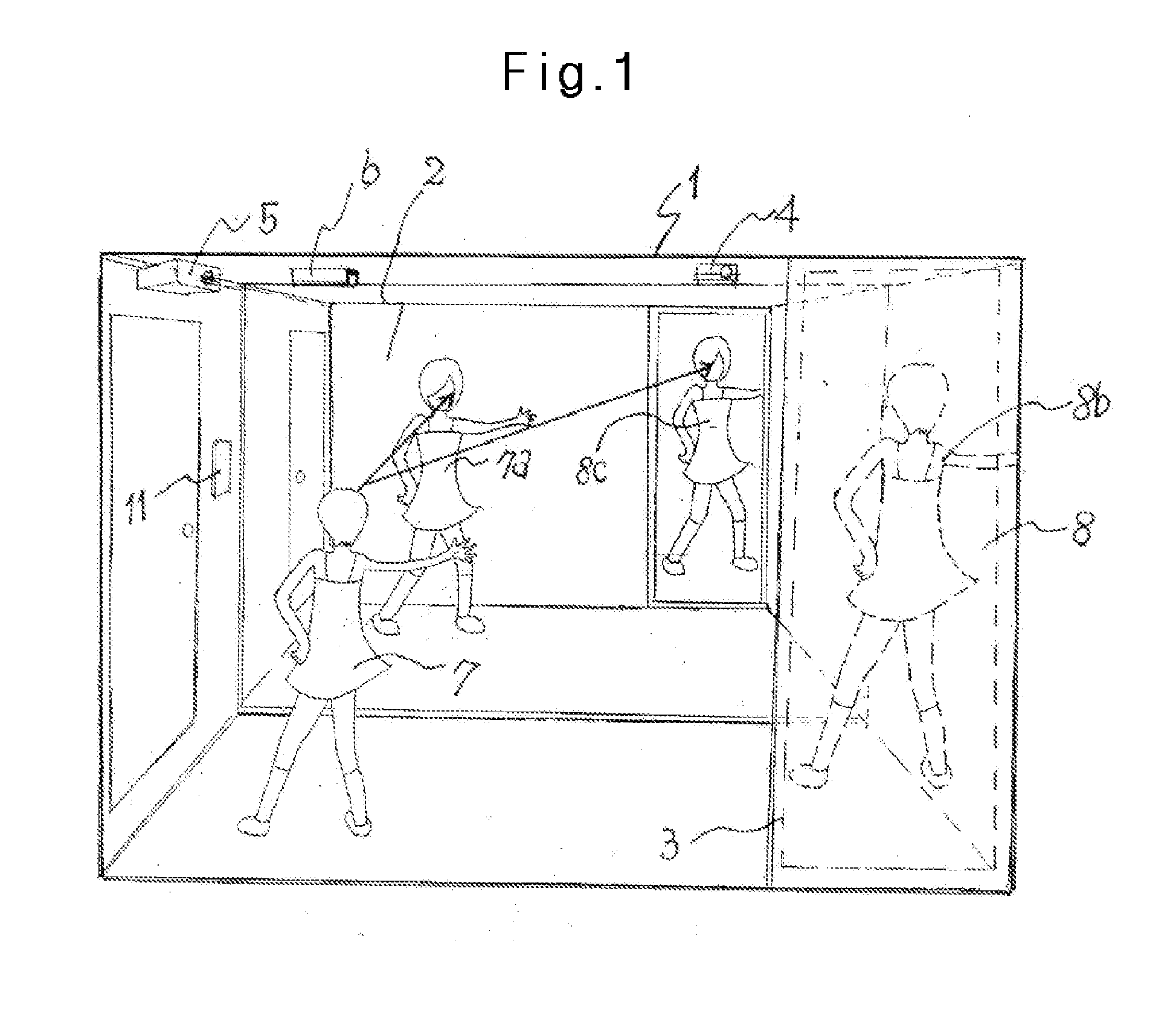
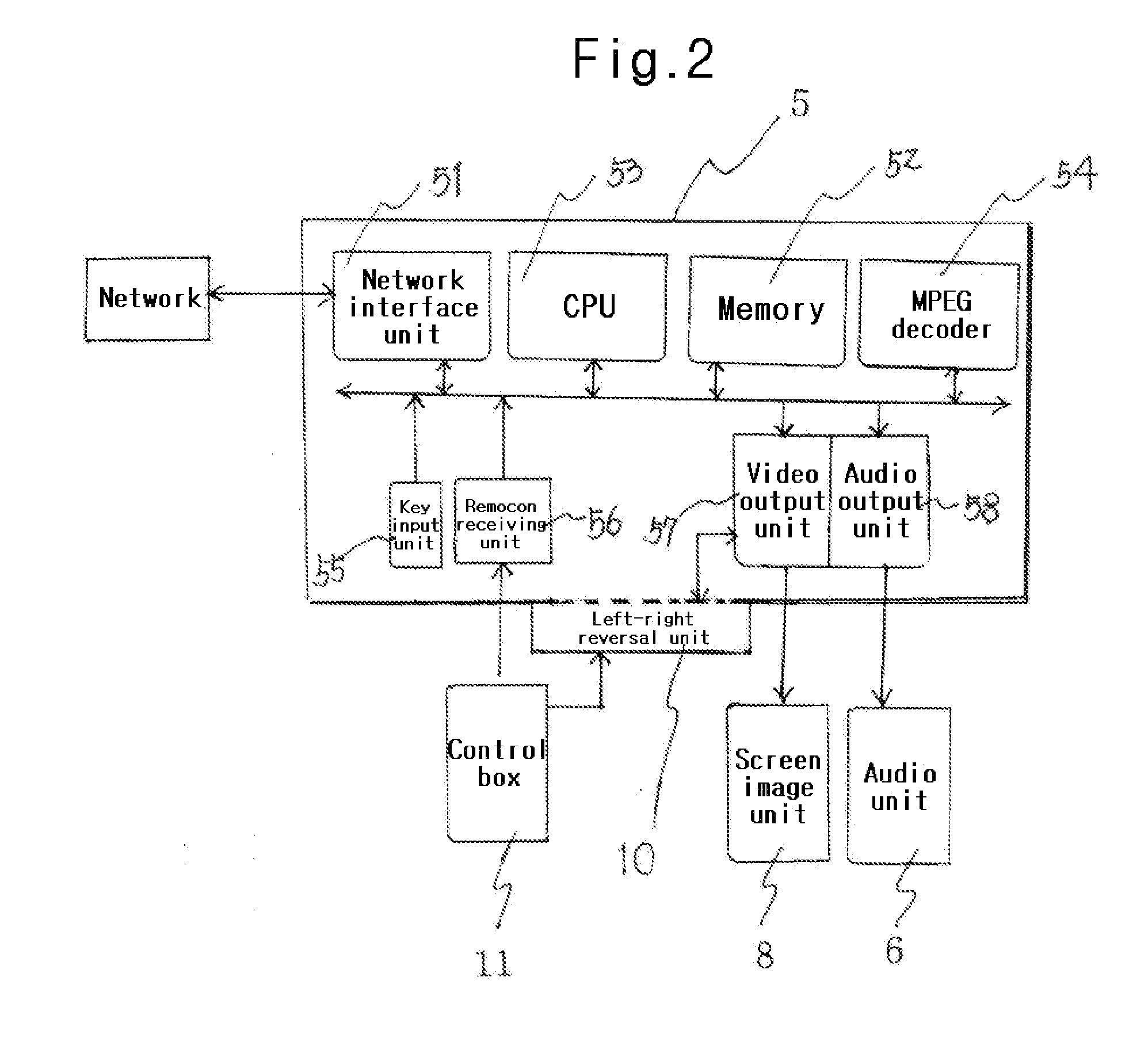
[0038]As shown in FIG. 5, the exercising room 1 having a proper area for personal dance exercising is provided and further a large mirror 2 is provided facing into the exercising room 1, with the screen image unit 8 being provided on one side of and on the same wall as the large mirror 2. In addition, the audio unit 6 and the image storage unit 5 are provided on left and right sides of the exercising room 1 and the controller 11 is provided inside the exercising room 1. At this time, the dance exercising image 8b shown in the mirror 2 is displayed in a state of the left-right sides being reversed with the left-right sides of the image being reversed through the left-right reversal unit 10.
second embodiment
[0039]The system for screen dance studio according to the present invention also may be in the form of a movable kiosk 14, as shown in FIG. 7.
[0040]That is, a kiosk 14 having a proper area for exercise dancing may be provided and a large mirror 2 may be provided on one inside wall of the kiosk. Here, the screen image unit 8 may comprise a plain image unit such as a screen 3, with the projector 4 or PDP provided facing one side of the large mirror 2 and further with the audio unit 6 and the image storage unit 5 provided on the respective left and right ends inside the kiosk 14, and with the controller 11 also provided inside the kiosk.
[0041]Accordingly, since the system for the screen dance studio is formed as a kiosk 14, there is no need for installing a sound proof wall and further size reduction is possible, causing production cost to be decreased. Meanwhile, a manufacturer can efficiently fabricate the system as the kiosk 14 unit and an installer can easily move the system as a k...
third embodiment
[0042]As shown in FIGS. 5 and 6, the screen image unit 8 may be added to the inside of the mirror 2 and thus the mirror 2 and the screen image unit may be integrated.
[0043]That is, the screen image unit 8 may be bonded to the inside of single plate mirror 2. As shown in FIG. 6(a). When a separate reflection mirror 2c is connected to upper and lower parts, or left and right sides, respectively separated, from the screen image unit 8, as shown in prior mirrors like FIG. 6(b), the reflection angle of the respective separation reflection mirror 2c is different, and thus it needs much time and effort to create a single reflection angle and further joining of the respective reflection mirror appears to decrease uniformity of single plate mirror. Accordingly, through the configuration as shown in FIG. 6(a) the aforementioned drawback can be solved.
[0044]The aforementioned single plate mirror may be configured as shown in FIGS. 8(a) and 8(b), that is, the screen image unit 8 is configured s...
PUM
 Abstract
Description
Claims
Application Information
 - R&D
- Intellectual Property
- Life Sciences
- Materials
- Tech Scout
- Unparalleled Data Quality
- Higher Quality Content
- 60% Fewer Hallucinations
Browse by: Latest US Patents, China's latest patents, Technical Efficacy Thesaurus, Application Domain, Technology Topic, Popular Technical Reports.
© 2025 PatSnap. All rights reserved.Legal|Privacy policy|Modern Slavery Act Transparency Statement|Sitemap|About US| Contact US: help@patsnap.com


