Photovoltaic module support clamp assembly

Active Publication Date: 2012-04-05
BEIJING APOLLO DING RONG SOLAR TECH
View PDF10 Cites 15 Cited by
  • Summary
  • Abstract
  • Description
  • Claims
  • Application Information

AI Technical Summary

Benefits of technology

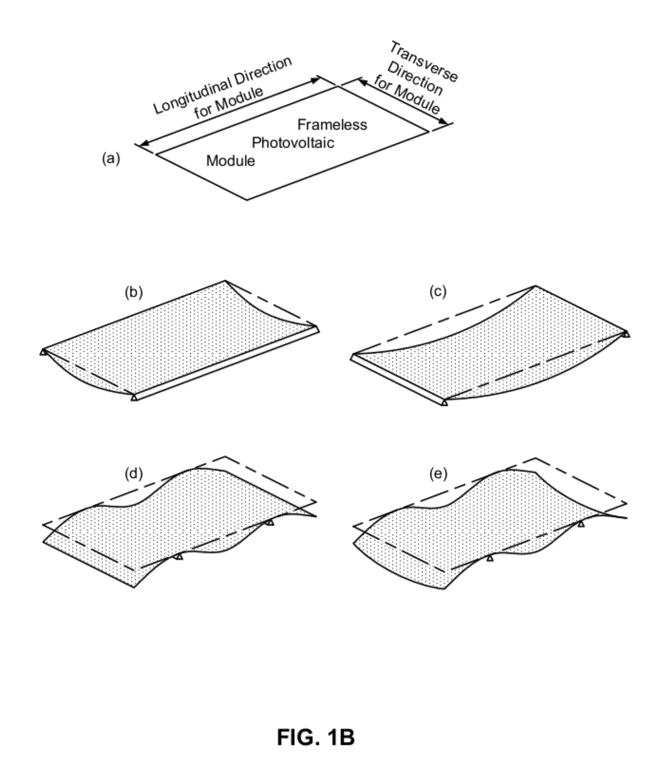
[0002]The invention relates generally to apparatus and techniques for mounting frameless photovoltaic modules to reduce module stress induced by the mounting configuration. The invention involves mounting clamps and rail spacing configured to relieve module stress by reducing or eliminating module sag.

Problems solved by technology

This can be challenging for frameless photovoltaic modules.

Method used


Image

  • Photovoltaic module support clamp assembly
  • Photovoltaic module support clamp assembly
  • Photovoltaic module support clamp assembly

Examples


example installation process

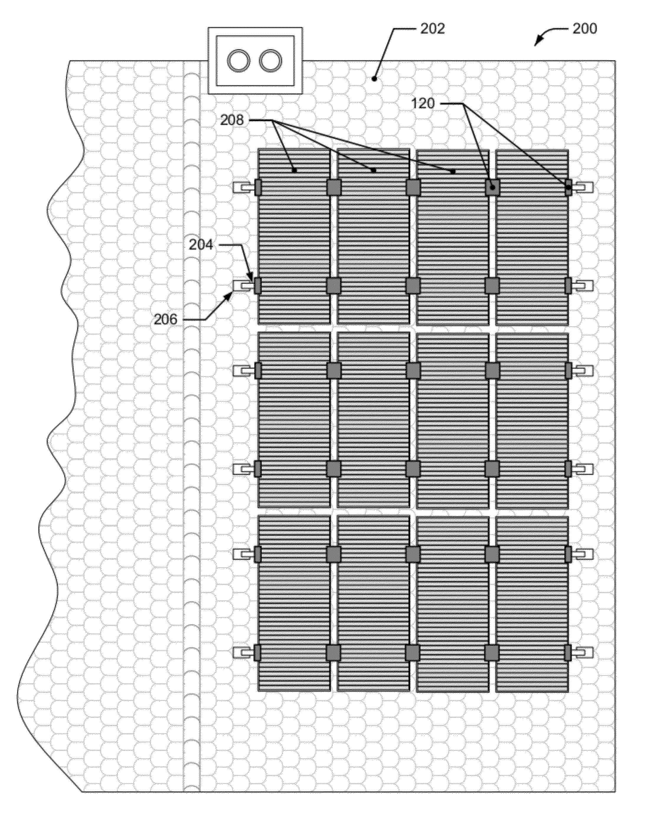
[0051]An example installation process utilizing mounting rail systems in conjunction with L-clamps is diagrammed in FIG. 5. It should be noted that not all of the operations depicted and described are necessarily part of a process in accordance with the present invention; an installation process in accordance with the invention may include all or just some of the operations described. A number of the operations are provided for context to facilitate description and understanding of the invention, but are optional in some embodiments.

[0052]Installation process 500 begins with the installation of mounting rails onto a support structure. This may include attaching one or more mounting rails to a roof, carport, or other support structure. Standoffs and mounting hardware may be used to implement the attachment. In the case of a pre-existing mounting rail installation, such as in a retrofit, re-installation of the mounting rails may not be necessary.

[0053]In step 510, the mounting rails m...


PUM

PropertyMeasurementUnit
Fractionaaaaaaaaaa
Thicknessaaaaaaaaaa
Thicknessaaaaaaaaaa

Abstract

Apparatus and techniques for mounting frameless photovoltaic modules reduce module stress induced by the mounting configuration. Mounting clamps and rail / clamp spacing configured to relieve module stress by reducing or eliminating module sag are used.

Description

BACKGROUND OF THE INVENTION[0001]Photovoltaic cells are widely used for generation of electricity, with multiple photovoltaic cells interconnected in module assemblies. Such modules may in turn be arranged in arrays and integrated into building structures or otherwise assembled to convert solar energy into electricity by the photovoltaic effect. Arrays of modules are typically mounted on racking systems on the roofs of buildings or on ground-based structures. The modules are required to pass load testing to ensure that they can safely withstand snow loading and other environmental conditions. This can be challenging for frameless photovoltaic modules.SUMMARY OF THE INVENTION[0002]The invention relates generally to apparatus and techniques for mounting frameless photovoltaic modules to reduce module stress induced by the mounting configuration. The invention involves mounting clamps and rail spacing configured to relieve module stress by reducing or eliminating module sag.[0003]In on...

Claims


Application Information

Patent Timeline
IPC IPC(8): H01L31/048H01L31/18
CPCF24J2/5205F24J2/5258Y02B10/12H02S20/23Y02E10/47H02S20/00Y10T29/49355Y02B10/20F24S2025/016F24S25/33F24S25/636Y02E10/50Y02B10/10
Inventor HARDIKAR, KEDARKHAN, ASHRAFBALYON, ROGER
Owner BEIJING APOLLO DING RONG SOLAR TECH
Why Eureka
Try Eureka