Filter Having Drain Valve With Mechanical Lock

Active Publication Date: 2012-04-19
BALDWIN FILTERS
View PDF1 Cites 8 Cited by
  • Summary
  • Abstract
  • Description
  • Claims
  • Application Information

AI Technical Summary

Benefits of technology

[0003]In view of the above, embodiments of the present invention provide a filter with a drain valve assembly that overcomes existing problems in the art. More particularly, embodiments of the present invention provide a drain valve assembly that incorporates a mechanical lock between a knob and a valve member thereof. With such a configuration, there is a reduced likelihood that the knob will become dislodged from the valve member in the field.

Problems solved by technology

As a result, the above filters often include drain valves to effectuate drainage of the water and other contaminants.

Method used


Image

  • Filter Having Drain Valve With Mechanical Lock
  • Filter Having Drain Valve With Mechanical Lock
  • Filter Having Drain Valve With Mechanical Lock

Examples


Embodiment Construction

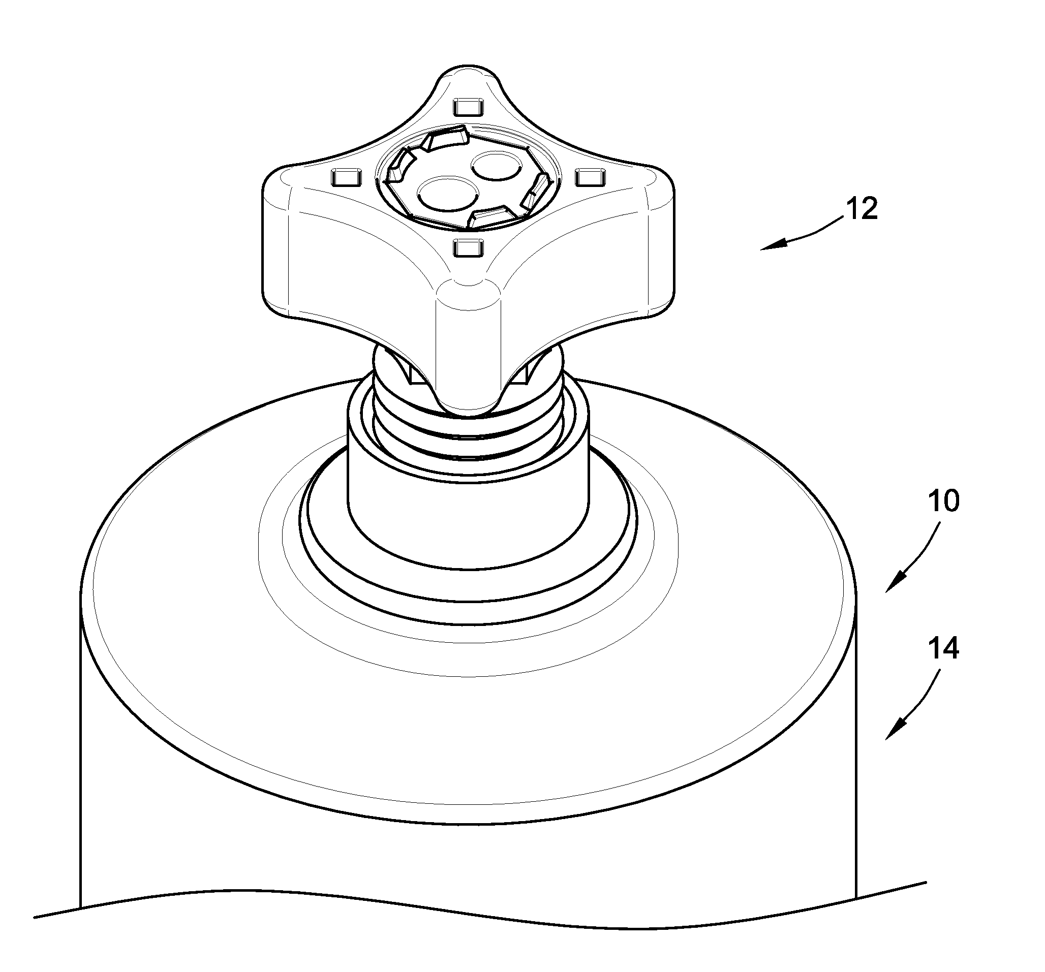
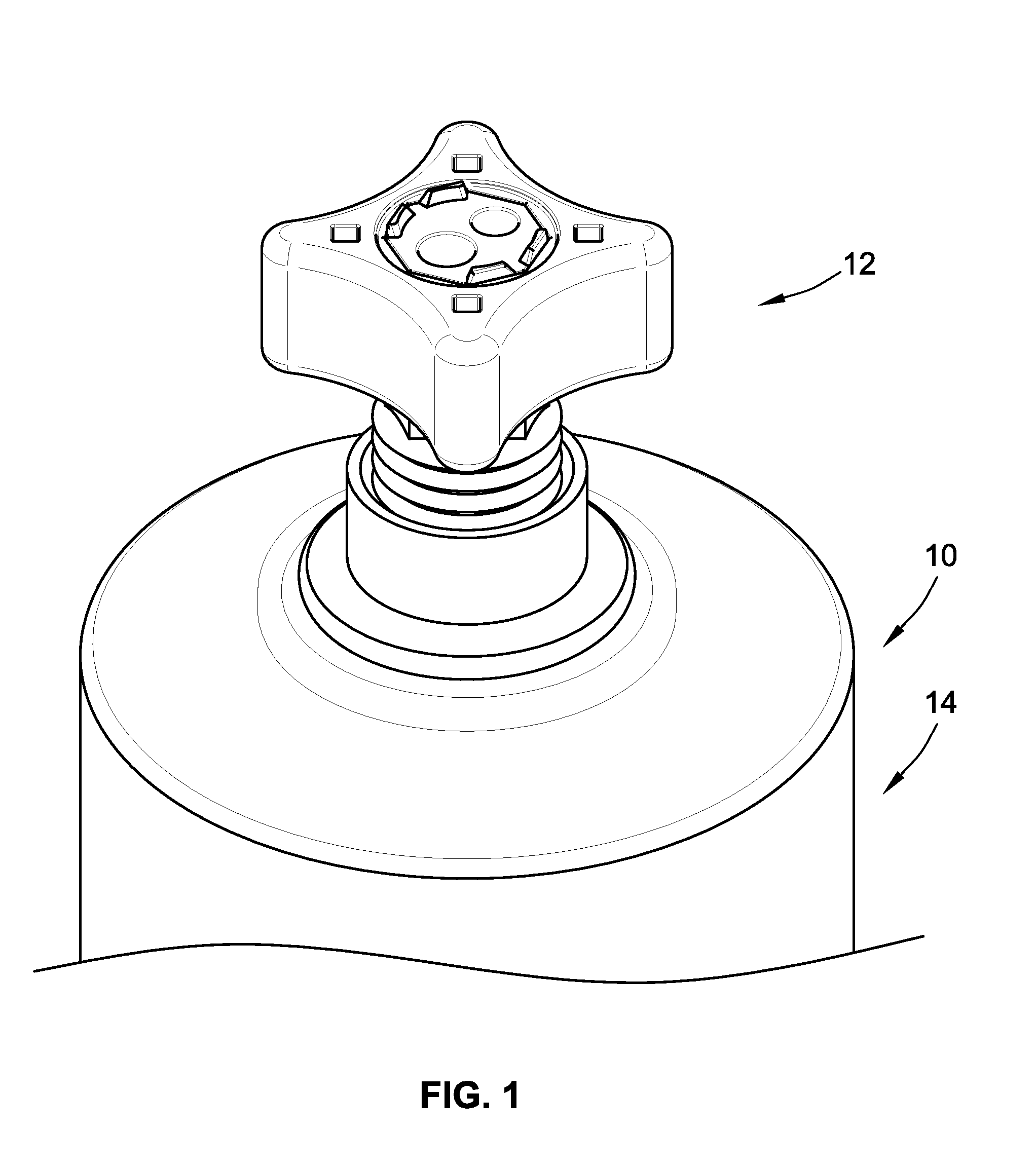
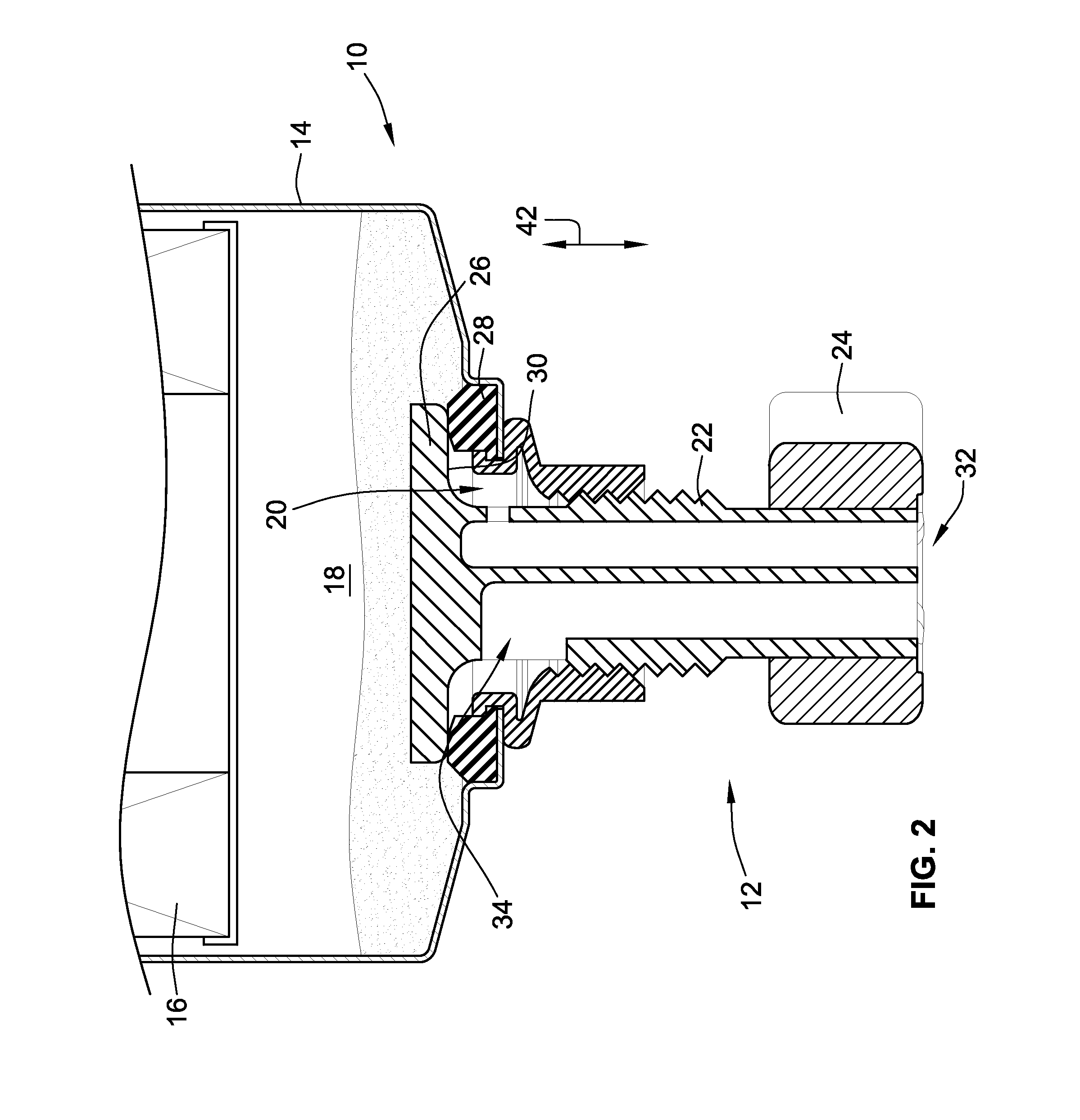
[0015]Turning now to the drawings, there is illustrated in FIG. 1 an exemplary embodiment of a filter 10 incorporating a drain valve assembly 12 mounted to a housing 14 of the filter 10 according to the present invention. As will be discussed in greater detail in the following, the drain valve assembly 12 allows for periodic draining of water and other contaminants collected within the housing 14 during filtration. With reference to FIG. 2, the housing 14 has a canister portion that carries filter media 16 within a chamber 18 therein. During the filtration process, water and other contaminants will collect in a bottom of the chamber 18 as illustrated. Periodically, the water and other contaminants within the chamber 18 must be drained to ensure the efficient and effective operation of the filter 10. As will be discussed in greater detail below, a user of the filter 10 can selectively open and close the drain valve assembly 12 by hand to facilitate such drainage.

[0016]Still referring...


PUM

PropertyMeasurementUnit
locking structureaaaaaaaaaa
rotationaaaaaaaaaa
Movementaaaaaaaaaa

Abstract

A filter with a drain valve is provided. The drain valve mounts within an opening of a housing of the filter. The drain valve has a knob mounted to a valve member thereof. At least one locking structure is disposed between the knob and the valve member to mechanically lock the knob to the valve member. Such a configuration reduces the likelihood that the knob will become inadvertently dislodged during operation.

Description

FIELD OF THE INVENTION[0001]This invention generally relates to fuel / water separators and more particularly to drain valves associated therewith.BACKGROUND OF THE INVENTION[0002]Fuel / water separation filters are commonly used in contemporary internal combustion engines. As fuel flows through the filter, water and other contaminants are separated from the fuel and collect in a chamber of the filter. Periodically, the water and other contaminants must be drained from the filter. As a result, the above filters often include drain valves to effectuate drainage of the water and other contaminants. One such filter incorporating a drain valve can be found at U.S. Pat. No. 5,144,978 to Brown et al., the entire disclosure of which is incorporated herein by reference. Embodiments of the present invention generally relate to improvements in the design and function of the aforementioned filters.BRIEF SUMMARY OF THE INVENTION[0003]In view of the above, embodiments of the present invention provid...

Claims


Application Information

Patent Timeline
Patent Type & Authority Applications(United States)
IPC IPC(8): B01D35/30
CPCB01D36/006B01D36/001F02M37/24B01D29/92B01D35/30F02M37/22
Inventor SCHWEITZER, STEPHENBENDIX, MITCH
Owner BALDWIN FILTERS
Why Eureka
Try Eureka