
Bottom Entry Sauna, Steam Room, Steam Egg

a sauna and bottom entry technology, applied in the field of bottom entry saunas, steam rooms, steam eggs, can solve the problems of frustrated 20 or more minutes a day, and achieve the effect of cooling down the room

Active Publication Date: 2013-02-21
PARKER MICHAEL G
View PDF22 Cites 7 Cited by
  • Summary
  • Abstract
  • Description
  • Claims
  • Application Information

AI Technical Summary

Benefits of technology

The Bottom Entry Sauna, Steam Room, and Steam Egg offer a solution for heat loss in traditional saunas caused by side entrances. By locating the point of entry and egress on the bottom of the structure, the sauna or therapeutic room is lifted off the floor, creating an aperture for entry and exit. This eliminates heat loss when individuals enter or exit. Additionally, the invention helps create a more positive experience for those who can handle the heat for both short and long durations, as they are less frustrated with those who quickly enter and exit.

Problems solved by technology

Additionally, for those individuals who enter and exit a heated therapeutic room after just a few minutes, those who stay for twenty or more minutes often become frustrated with those who are quick to enter and soon thereafter exit, as it cools down the room with every ingress and egress.

Method used


Image

  • Bottom Entry Sauna, Steam Room, Steam Egg
  • Bottom Entry Sauna, Steam Room, Steam Egg
  • Bottom Entry Sauna, Steam Room, Steam Egg

Examples


Embodiment Construction

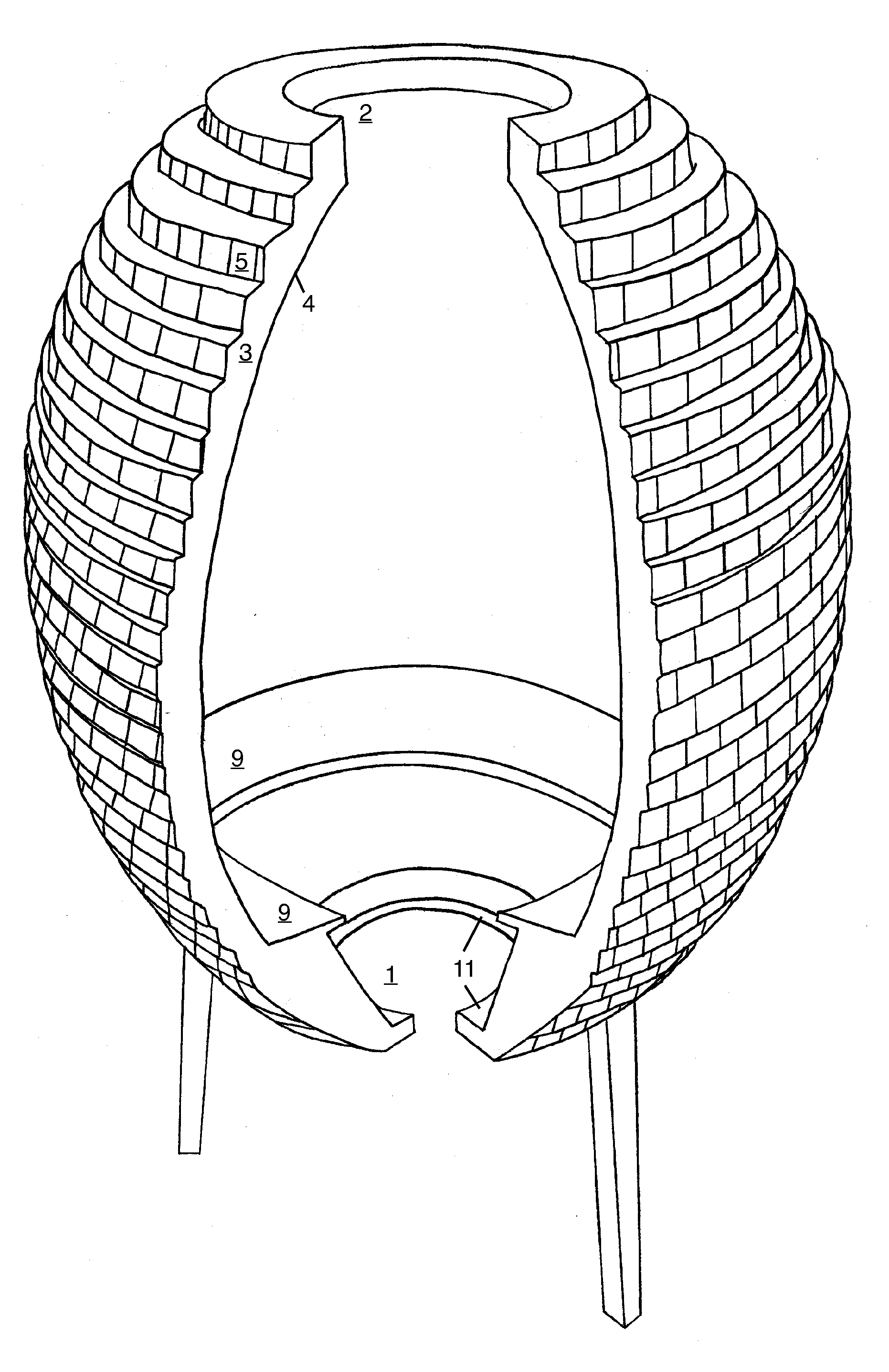
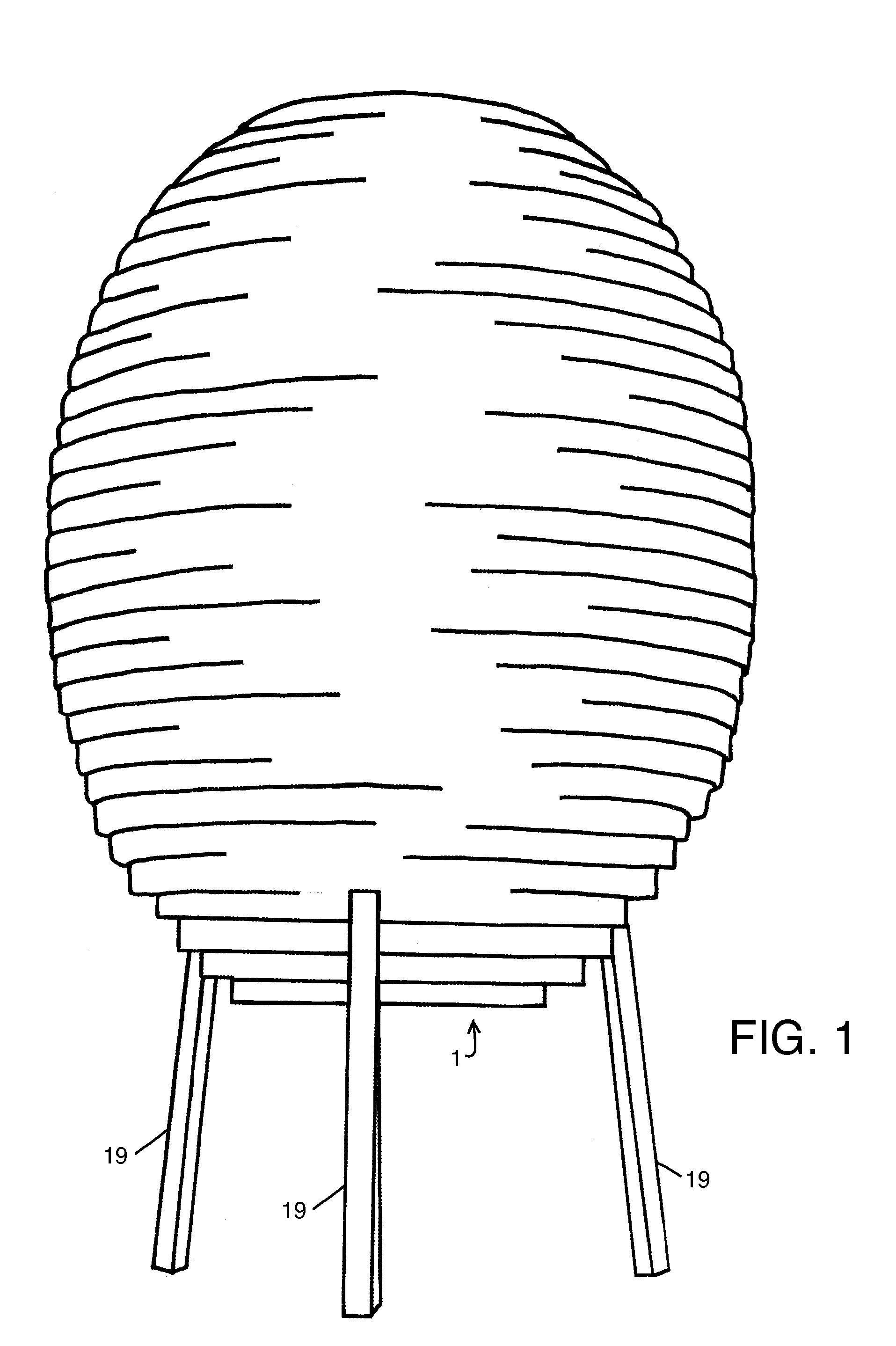
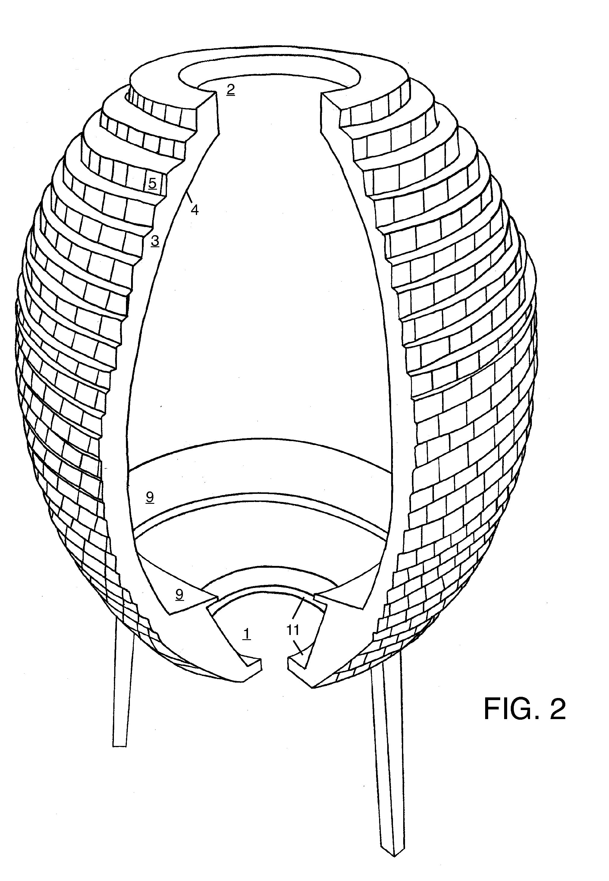
[0077]The bottom entry sauna, steam room, steam egg, or therapeutic room consists of a structural shift in relocating the paradigm of the ingress and egress points into a therapy room so that the ingress and egress door becomes located on the floor 1 of said structure FIG. 1-8. The invention rose out of the desire to solve the problem of wasted energy loss and wasted space in the field of saunas and therapy chambers. The prior art's side door entry allows much heat to escape each time the door opens and closes. The prior art's side door also reduces the quantity of seating available within these generally small heated spaces. The invention of the Bottom Entry Sauna, Steam Room, Steam Egg solves these problems and lays a foundation for future improvements in the use of these forms, but not limited to other restorative and health promoting chambers, as requirements for energy efficiency and space efficiency become more attractive to both consumers and producers. The first embodiment F...


PUM


Abstract

The invention disrupts the paradigm of the side entrance within the field of saunas, steam rooms and therapeutic chambers. The invention reorients the entrance from a door in the side of a therapeutic chamber, as is the situation in the prior art, and places the point of ingress and egress to the bottom or floor of the chamber. Without a side entry door, much less heat is lost when individuals enter and exit the chamber. Furthermore, this invention creates the opportunity for 360 degree seating in steam rooms and saunas, which is exemplified in the embodiment of the prototype named Steam Egg, which is a ten and a half foot tall freestanding egg shaped, mirror covered, steam room that is entered through a hole in the bottom, hovering 33.5 inches off the ground stabilized on three steel legs.

Description

CROSS-REFERENCE TO RELATED APPLICATIONS[0001]This non-provisional utility patent refers to the provisional patent application number U.S. 61 / 525,157 filed on Aug. 18, 2011 by the small entity independent inventor, Michael G. Parker in Los Angeles, Calif. 90013.PRIOR ART U.S. PATENT DOCUMENTS CITED[0002]U.S. Pat. No. 871,074[0003]Nov. 12, 1907[0004]Stockton[0005]Bath Apparatus[0006]U.S. Pat. No. 1,979,094[0007]Oct. 30, 1934[0008]Blunt[0009]Knock-Down Heat Bath Appliance[0010]U.S. Pat. No. 5,628,073[0011]May 13, 1997[0012]Popovich[0013]Sauna[0014]U.S. Pat. No. 3,271,786[0015]Sep. 13, 1966[0016]Joy[0017]Portable Sauna Cabinet[0018]U.S. Pat. No. 3,368,575[0019]Feb. 13, 1968[0020]Besonen[0021]Portable Collapsible Shelter[0022]U.S. Pat. No. 3,419,915[0023]Jan. 7, 1969[0024]Clark[0025]Heat Bath Appliance[0026]U.S. Pat. No. 3,889,698[0027]Jun. 17, 1975[0028]Roessl[0029]Portable Shelter[0030]U.S. Pat. No. 4,277,855[0031]Jul. 14, 1981[0032]Poss[0033]Portable Sauna[0034]U.S. Pat. No. 3,422,465...

Claims


Application Information

Patent Timeline
Patent Type & Authority Applications(United States)
IPC IPC(8): A61H33/06
CPCA61H33/066A61H2201/10A61H2201/102A61N2005/0668A61N2005/064A61N2005/0652A61N2005/0663
Inventor PARKER, MICHAEL G.
Owner PARKER MICHAEL G
Learn More