Labyrinth seal system

a technology of seal system and lint, which is applied in the direction of engine seals, leakage prevention, machines/engines, etc., can solve the problems of reducing the effectiveness of seals

Inactive Publication Date: 2012-04-19
GENERAL ELECTRIC CO
View PDF20 Cites 21 Cited by
  • Summary
  • Abstract
  • Description
  • Claims
  • Application Information

AI Technical Summary

Benefits of technology

[0004]A labyrinth seal system is disclosed, including a stationary component having a plurality of radially inwardly projecting, axially spaced teeth extending therefrom; and a rotor having a plurality of radially outwardly projecting, axially spaced protrusions, each protrusion having a low pressure side and a high pressure side, wherein the low pressure side of at least one protrusion extends farther in a radial direction than the high pressure side.
[0005]A first aspect of the disclosure provides a labyrinth seal system comprising: a stationary component having a plurality of radially inwardly projecting, axially spaced teeth extending therefrom; and a rotating component having an outer surface proximate to the plurality of teeth, wherein the outer surface includes a plurality of radially outwardly projecting, axially spaced protrusions, each protrusion having a low pressure side and a high pressure side, wherein the low pressure side of at least one protrusion extends farther in a radial direction than the high pressure side.

Problems solved by technology

If the teeth and the raised chamfers are not lined up, i.e., axially aligned, operating fluid is allowed to flow more easily through the seal, thereby reducing the effectiveness of the seal.

Method used


Image

  • Labyrinth seal system
  • Labyrinth seal system
  • Labyrinth seal system

Examples


Embodiment Construction

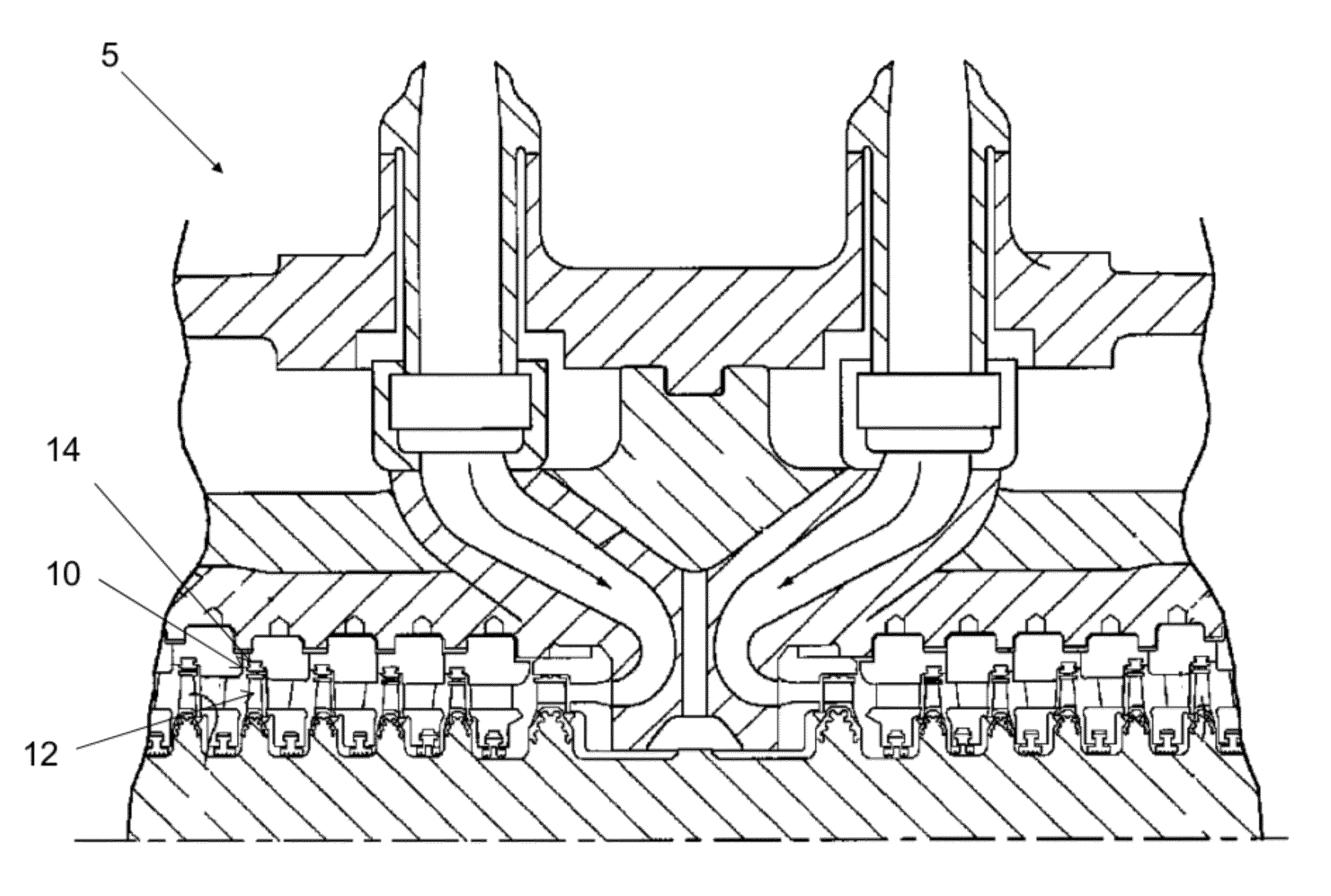
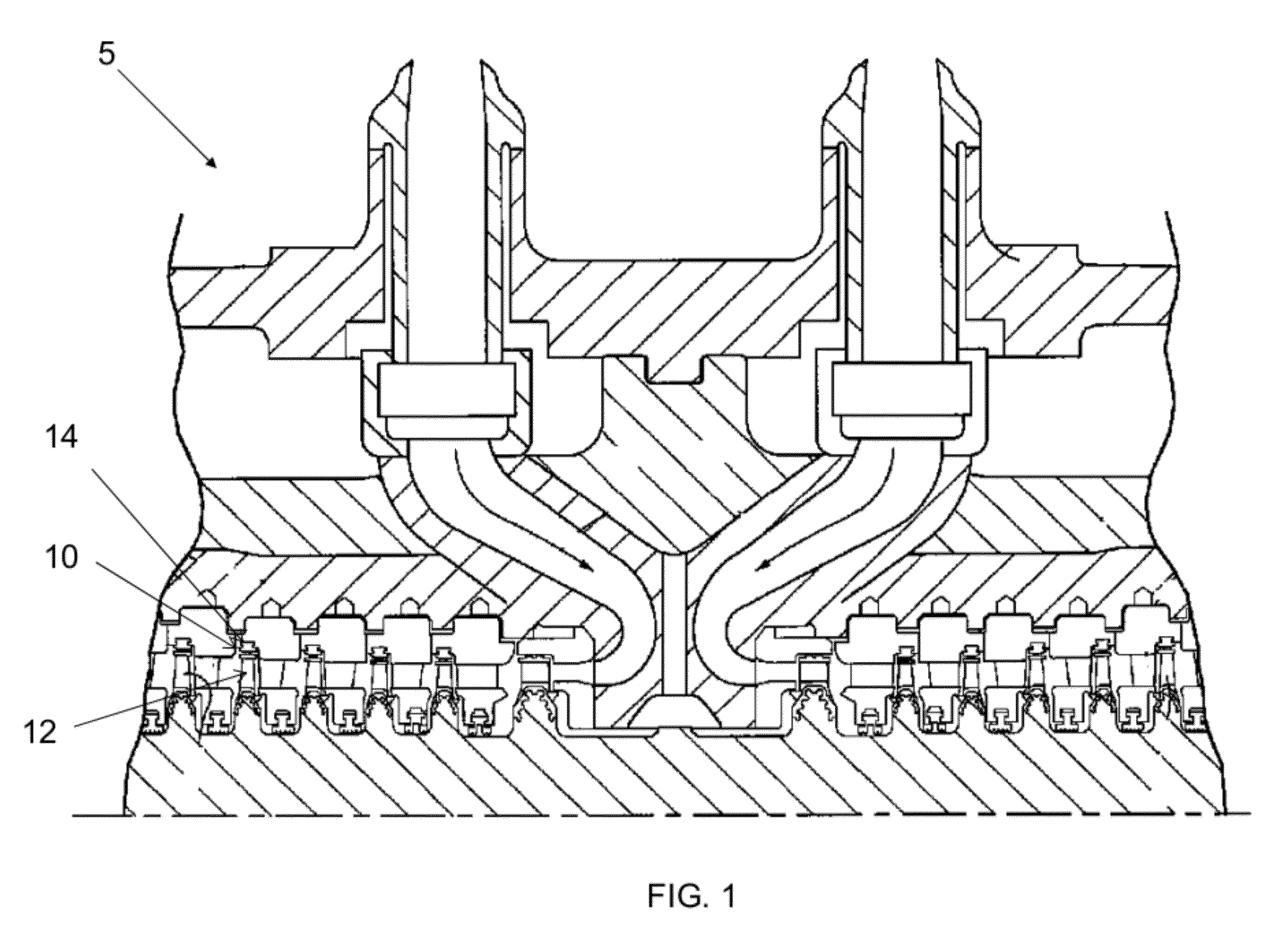
[0017]Turning to FIG. 1, a portion of a turbomachine 5 is shown. Turbomachine 5 includes a plurality of labyrinth seal systems 10 to provide a seal between a rotating component 12 and a stationary component 14. One such labyrinth seal system 10, as known in the art, is shown in FIG. 2.

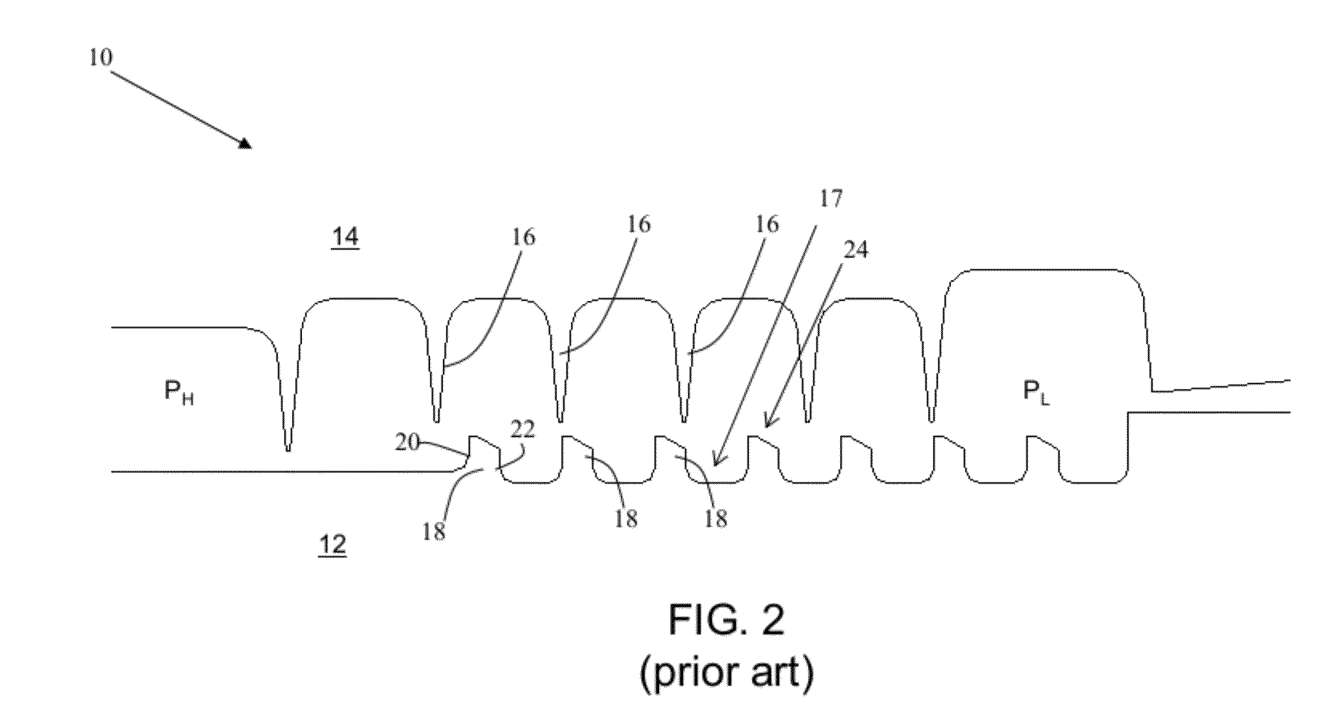
[0018]Turning to FIG. 2, a labyrinth seal system 10 as known in the art is shown. Seal system 10 has a high pressure side, PH, and a low pressure side, PL. Operating fluid from a turbomachine 5 (FIG. 1) flows through seal 10 from high pressure side, PH, to low pressure side, PL. As known in the art, seal system 10 includes a stator 14 and a rotor 12. As also known in the art, seal system 10 is a labyrinth seal, i.e., it has a plurality of radially inwardly projecting, axially spaced teeth 16 extending from stationary component 14. In addition, seal system 10 includes a rotor 12 having a rotor land 17, i.e., an outer surface, proximate to teeth 16, including a plurality of radially outwardly projecting,...


PUM


Abstract

A labyrinth seal system is disclosed, including a stationary component having a plurality of radially inwardly projecting, axially spaced teeth extending therefrom; and a rotor having a plurality of radially outwardly projecting, axially spaced protrusions, each protrusion having a low pressure side and a high pressure side, wherein the low pressure side of at least one protrusion extends farther in a radial direction than the high pressure side.

Description

BACKGROUND OF THE INVENTION[0001]The disclosure relates generally to rotary turbomachines, and more particularly, to a labyrinth seal system for use in a turbomachine.[0002]In rotary machines such as turbines, seals are provided between rotating and stationary components. For example, in steam turbines, it is customary to provide a plurality of arcuate packing ring segments to form an annular labyrinth seal between the stationary and rotating components. Typically, the arcuate packing ring segments (typically, four to six per annular seal) are disposed in an annular groove in the stationary component concentric to the axis of rotation of the machine and hence concentric to the sealing surface of the rotating component. Each arcuate seal segment carries an arcuate seal face in opposition to the sealing surface of the rotating component. In labyrinth type seals, the seal faces carry a radially directed array of axially spaced teeth, in which teeth are radially spaced from an array of ...

Claims


Application Information

Patent Timeline
Patent Type & Authority Applications(United States)
IPC IPC(8): F16J15/447
CPCF01D11/02F16J15/4472F05D2220/31
Inventor NEELI, SUDHAKARJOHN, JOSHY
Owner GENERAL ELECTRIC CO
Why Eureka
Try Eureka