Anti-theft locking means for a vehicle steering shaft

a technology for steering shafts and anti-theft locks, which is applied in the direction of shafts, mechanical control devices, restricting/preventing/returning movement of parts, etc., can solve the problems of increasing the cost and the size of the locking system, destroying or degrading, etc., and avoiding deformation and/or destruction of components.

Active Publication Date: 2006-09-19
NACAM FRANCE S
View PDF10 Cites 9 Cited by
  • Summary
  • Abstract
  • Description
  • Claims
  • Application Information

AI Technical Summary

Benefits of technology

[0011]Accordingly, a primary object of the present invention is to provide a locking device that includes an annular locking sleeve arranged concentrically about the smooth outer circumferential surface of the steering shaft, which sleeve has a serpentine cross-sectional configuration, thereby to define successive smooth convex projections and concave valleys on the inner and outer peripheries of the sleeve. The sleeve is normally non-rotatably connected with the steering shaft owing to the provision of a predetermined frictional force between the inner convex projections on the sleeve and the circumferential surface of the steering shaft. When the locking sleeve is prevented from rotation by the insertion of a stationary locking arm into a locking slot on the outer periphery of the sleeve, upon overload the predetermined frictional force is overcome, thereby permitting the steering shaft to rotate relative to the sleeve, so that deformation and / or destruction of the components is avoided.
[0014]The transverse angular position of the teeth is independent of the transverse angular position of the radial interior convex projections, thereby to permit one to precisely adapt a number of interior convex shapes to the maximum torque to be transmitted, and so as to be able exactly to adapt the number and the transverse shape of the radial teeth to the automotive vehicle concerned.
[0018]The rotational torque-limiting locking device according to the present invention provides the advantage of a particularly simple assembly with a single sleeve. Moreover, it is possible to adapt that sleeve to various types of vehicles, since the position of the serpentine undulations is independent of the position of the axial slot that receives the locking arm of the locking device. Finally, the design of the annular sleeve with serpentine undulations makes it possible in a precise fashion to provide the desired precise value of the rotational torque force at which the shaft with the steering wheel turns with respect to the sleeve.

Problems solved by technology

These locking systems possess the drawback of possibly being destroyed or degraded by the rupture or bending of the locking bolt, thereby producing a dangerous driving condition accompanied by untimely locking of the steering shaft as a consequence of the deformed or disintegrated parts.
The different applications of this type of torque limiting system possess the drawback of employing either complex assemblies that require numerous components, thereby increasing the cost and the size of the locking system, or assemblies having a single sleeve whose torque is difficult to control or whose internal structure is tied to the external structure.

Method used


Image

  • Anti-theft locking means for a vehicle steering shaft
  • Anti-theft locking means for a vehicle steering shaft
  • Anti-theft locking means for a vehicle steering shaft

Examples


Embodiment Construction

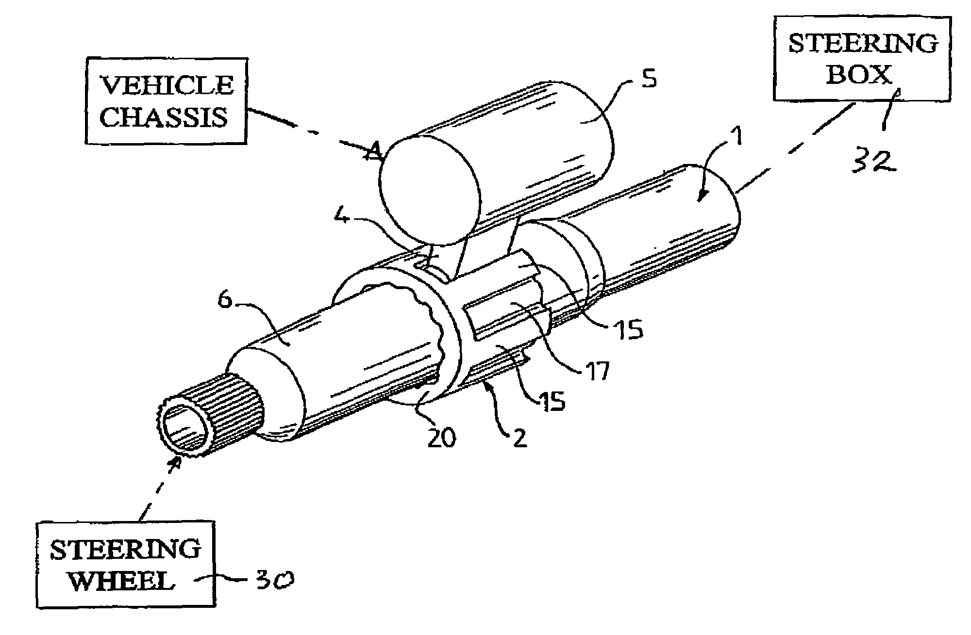
[0027]According to the present invention, a rotary torque limiting locking device is provided for use on the steering column of an automotive vehicle. The steering column comprises a steering shaft 1 connected at one end to the steering wheel 30 and at the other end to a steering box 32 that controls the front steering wheels of the vehicle.

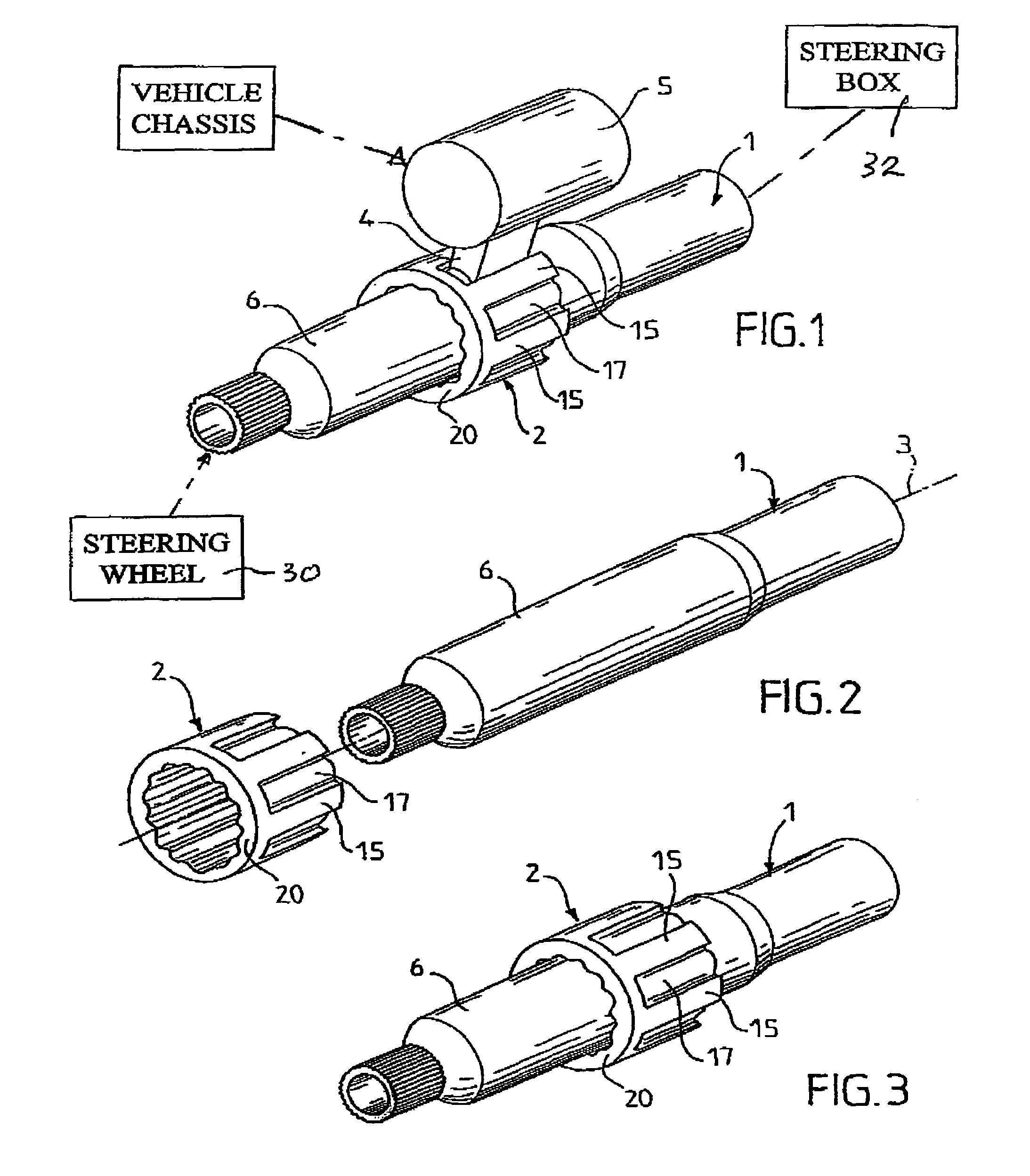
[0028]As shown in FIGS. 1–3, an annular locking sleeve 2 is mounted concentrically about the smooth cylindrical circumferential portion of the steering shaft 1. As will be described in greater detail below, locking sleeve 2 is adapted to cooperate with the locking arm 4 of a locking lock 5, which constitutes the antitheft device of the vehicle.

[0029]More particularly, locking sleeve 2 is mounted on a circular portion 6 of steering shaft 1 which rotates about the steering axis 3.

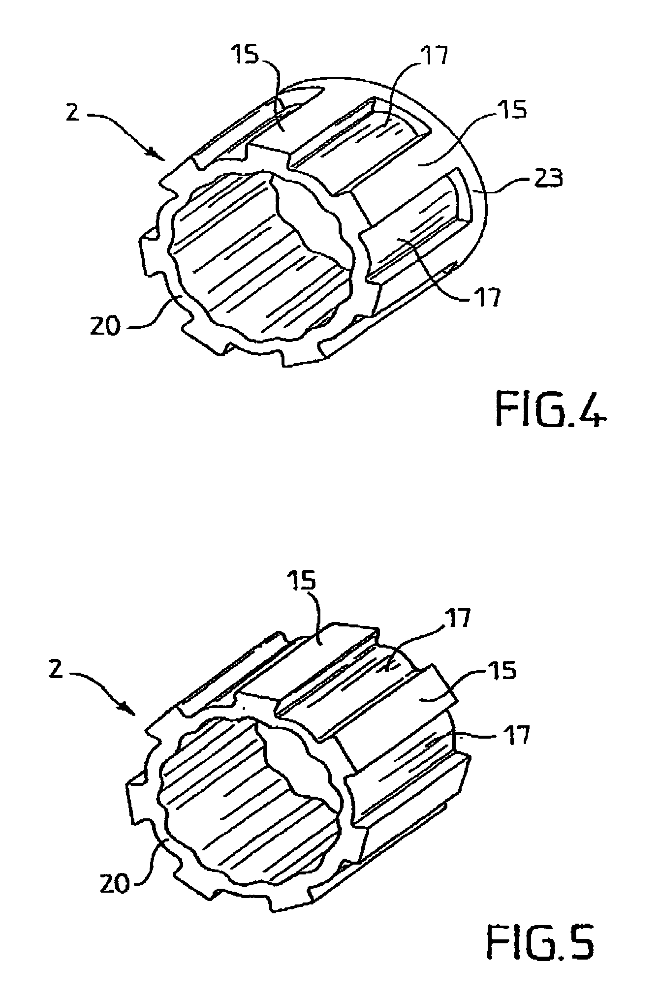
[0030]As shown in detail in FIGS. 4–7, locking sleeve 2 consists essentially of a tubular body portion 20 having an outer periphery 22 from which extend a plurality of rad...


PUM


Abstract

An anti-theft locking device for vehicles includes an annular locking sleeve mounted concentrically about and normally in frictional engagement with the vehicle steering shaft. The locking sleeve includes a body portion having a serpentine cross-sectional configuration, thereby defining on the inner periphery of the sleeve a plurality of alternate smooth convex projections and concave valleys. The convex projections are in frictional engagement with the circumferential surface of the steering shaft by a predetermined frictional force that is greater than the rotational torque force produced during normal steering operation of the vehicle. A plurality of circumferentially spaced teeth extend radially outwardly from the locking sleeve, thereby to define between the teeth a plurality of locking slots one of which is arranged to receive the free extremity of the locking arm of a locking device.

Description

BACKGROUND OF THE INVENTION[0001]1. Field of the Invention[0002]This invention relates to an anti-theft locking device adapted for mounting on the steering column of an automotive vehicle.[0003]2. Description of the Related Art[0004]It is well known in the patented prior art to provide a vehicle steering assembly including a steering column that is connected at one end with the vehicle steering wheel, the other end of the steering column being connected with the front steering wheels of the vehicle via steering box means.[0005]Anti-theft locking devices have been proposed that do not include any torque limiting means, such as, for example, a locking system including a locking bolt that engages a component that is integral with the steering column. These locking systems possess the drawback of possibly being destroyed or degraded by the rupture or bending of the locking bolt, thereby producing a dangerous driving condition accompanied by untimely locking of the steering shaft as a co...

Claims


Application Information

Patent Timeline
Patent Type & Authority Patents(United States)
IPC IPC(8): B60R25/02B60R25/021B62D1/16B62D5/30
CPCB60R25/02107Y10T70/5659Y10T70/5664
Inventor CHARTRAIN, MICHELJANVIER, ARNAUD
Owner NACAM FRANCE S
Why Eureka
Try Eureka