Gasket with a compression limiter

a compression limiter and gasket technology, applied in the direction of engine sealing, machine/engine, etc., can solve the problems of fatigue cracks forming in the area of compression beads, reducing the life and performance of engines, and reducing the life of engines. , to achieve the effect of preventing the full flattening of compression beads, low cost, and constant sealing pressur

Inactive Publication Date: 2013-08-01
FEDERAL MOGUL MOTORPARTS LLC
View PDF11 Cites 9 Cited by
  • Summary
  • Abstract
  • Description
  • Claims
  • Application Information

AI Technical Summary

Benefits of technology

[0006]According to one aspect of the invention, a multi-layer gasket for establishing a fluid-tight seal between a first member and a second member is provided which includes a compression limiter in the form of a stopper for preventing full flattening of a compression bead when the gasket is compressed between the first member, e.g. an engine block, and the second member, e.g. a cylinder head. The gasket has one or more layers, and the stopper has a gear-like shape and is integrally formed with one of the layers through an embossing process. Each tooth of the gear-shaped stopper extends upwardly from a plane by a distance which is less than the height of the compression bead if the gasket has a single layer or the combined heights of the compression beads if the gasket has multiple layers. Accordingly, both of the compression beads extend upwardly from the plane and remain elastically biased against one another, even if the cylinder head is over-loaded onto the engine block. As such, the compression beads are assured of maintaining a generally constant, high sealing pressure against one another, thereby providing and maintaining the gas-tight seal about the circumference of the cylinder bore. In addition to maintaining the desired gas-tight seal about the cylinder bore, the compression beads, by not being over-compressed and completely flattened, remain free from the formation of premature fatigue cracks both during assembly and while in use. Thus, for very little additional cost, the gasket is protected from full flattening of the compression bead, even if the cylinder head is over-loaded onto the engine block.

Problems solved by technology

Unfortunately, while fastening the cylinder head to the engine block, the compression bead can be over-compressed and substantially flattened.
If the compression bead is over-compressed, in addition to losing its ability to maintain a gas-tight seal, fatigue cracks can form in the area of the compression bead during the initial clamping or while in use.
If formed, fatigue cracks ultimately reduce the ability of the static gasket to maintain a gas-tight seal, thereby diminishing the life and performance of the engine.
These compression limiters are typically additional components and may either be costly to produce or may fully prevent flattening of the compression bead.

Method used


Image

  • Gasket with a compression limiter
  • Gasket with a compression limiter
  • Gasket with a compression limiter

Examples


Embodiment Construction

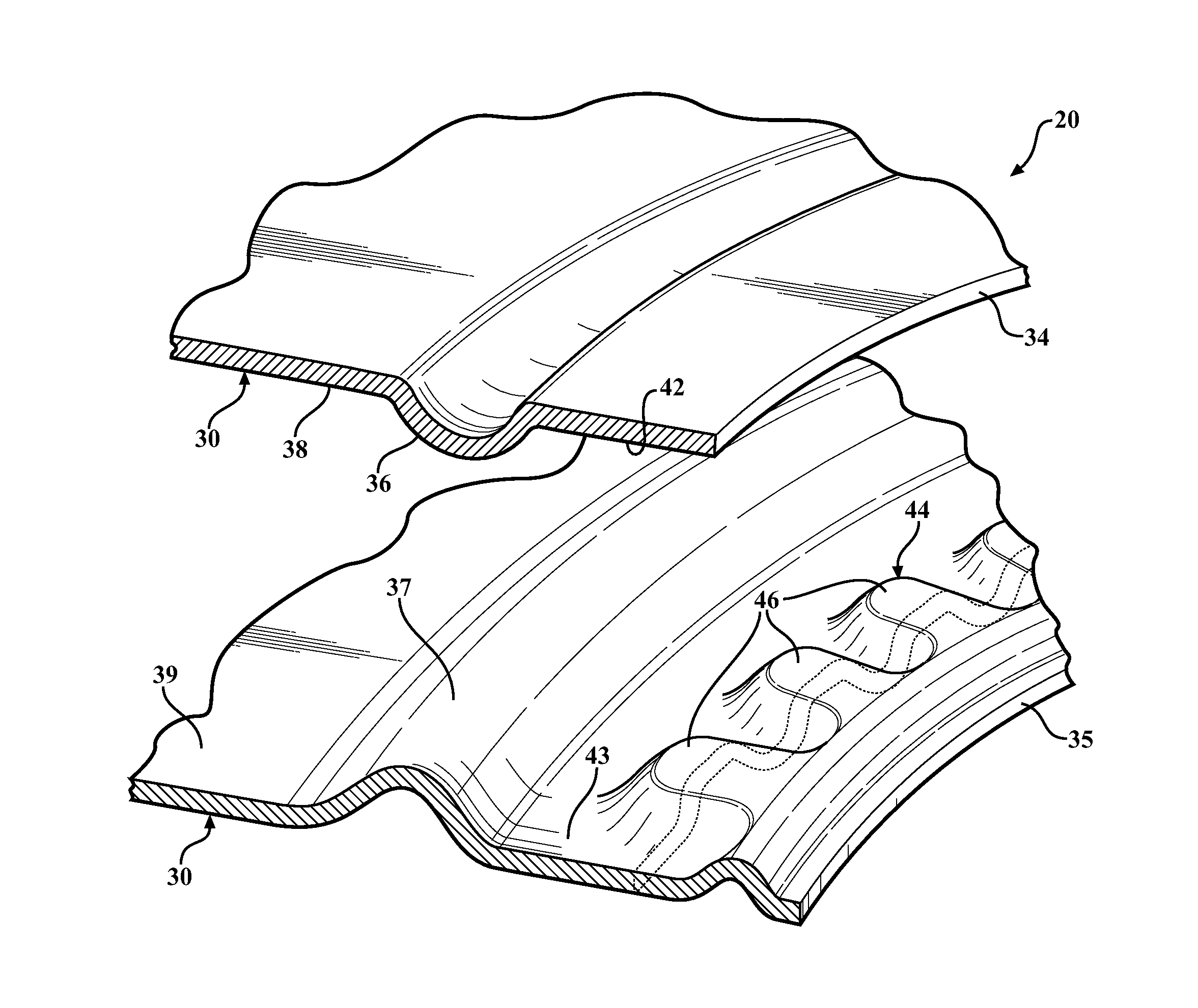
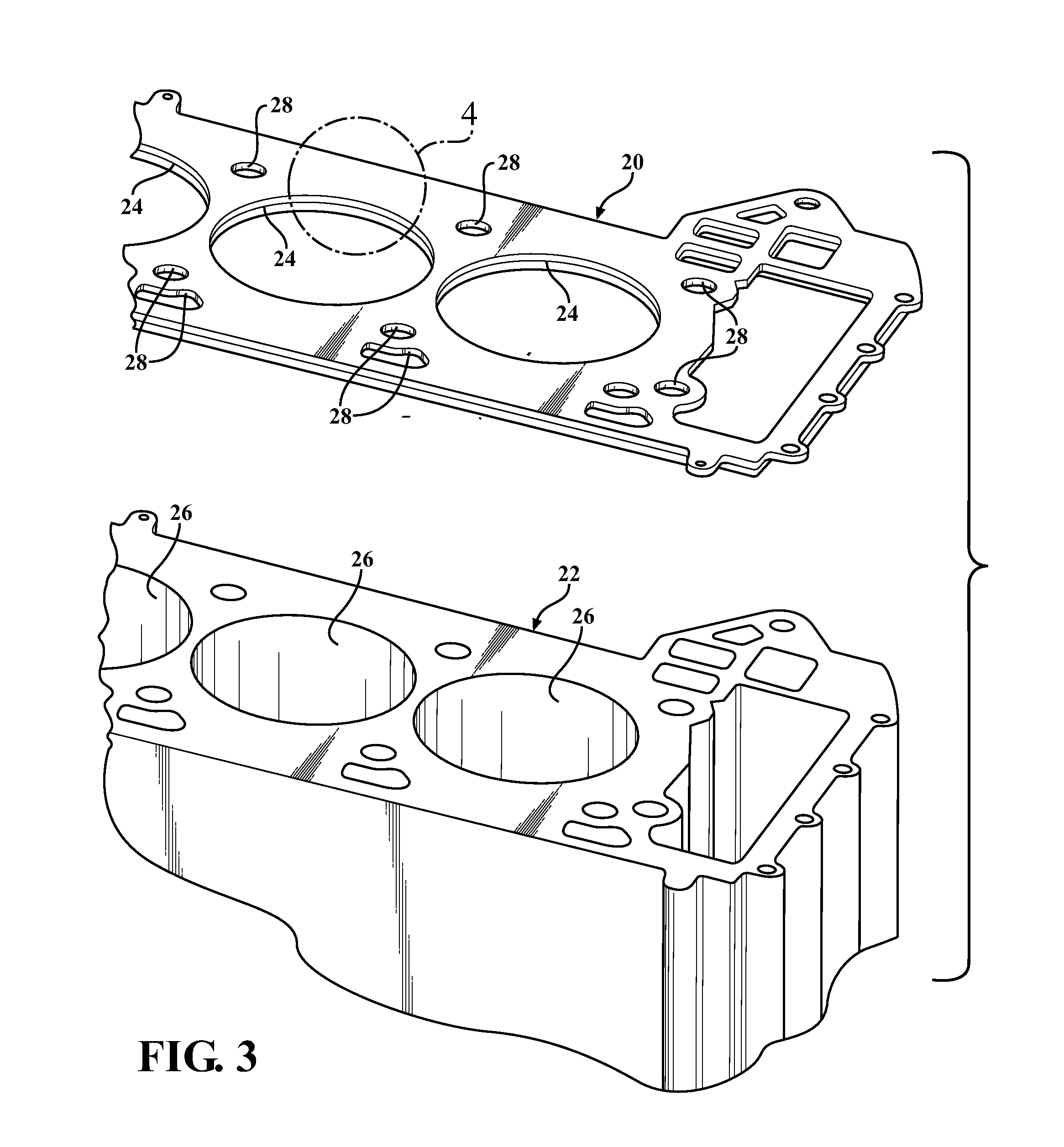
[0020]Referring to the Figures, wherein like numerals indicate corresponding parts throughout the several views, a gasket 20 configured for establishing a seal between a cylinder head (not shown) and an engine block 22 is generally indicated in FIG. 3. The exemplary gasket 20 includes a plurality of large, generally circular openings 24 which correspond with a plurality of cylinder bores 26 in the engine block 22. The gasket 20 also includes a plurality of holes 28 for allowing bolts or fasteners to extend through the gasket or for allowing coolant to flow between the engine block 22 and the cylinder head, as will be understood by those of ordinary skill in the art. Although the exemplary gasket 20 is a cylinder head gasket for use in an internal combustion engine, it should be appreciated that the gasket 20 could be used to seal any desirable members, not just a cylinder head and an engine block 22. Additionally, although each of the embodiments shown in the drawings and discussed ...


PUM


Abstract

A multi-layer gasket including first and second functional layers, each having an opening. Each of the functional layers includes a compression bead, and the compression beads contact and seal against one another when the gasket is compressed between a cylinder head and an engine block. At least one of the functional layers includes a stopper disposed between the compression bead and the opening. The stopper has a gear-like shape including a plurality of circumferentially spaced teeth. Each tooth extends upwardly from a plane by a distance which is less than the combined height of the compression beads. When the gasket is compressed between the cylinder head and engine block, the stopper ensures that the compression beads remain elastically biased against one another and maintain a gas-tight seal.

Description

BACKGROUND OF THE INVENTION[0001]1. Field of the Invention[0002]The invention relates to static gaskets of the type used to establish a gas-tight seal between two members to be clamped together, and more particularly to multi-layer gaskets such as cylinder head gaskets.[0003]2. Related Art[0004]In establishing a gas-tight seal between two members to be clamped together, such as a cylinder head and an engine block, it is common to use a static cylinder head gasket having multiple layers. Generally, at least one of the layers of the multi-layer gasket, sometimes referred to as a functional layer, has a compression bead to establish the fluid tight seal. Another of the layers, sometimes referred to as a distance layer, is configured to abut the functional layer in an effort to establish the gas-tight seal by compressing the compression bead of the functional layer. Unfortunately, while fastening the cylinder head to the engine block, the compression bead can be over-compressed and subs...

Claims


Application Information

Patent Timeline
Patent Type & Authority Applications(United States)
IPC IPC(8): F02F11/00
CPCF16J15/0825F02F11/002F16J15/022
Inventor FRACZ, MARCINZWICK, JIMLESNAU, IV, EDWARD
Owner FEDERAL MOGUL MOTORPARTS LLC
Why Eureka
Try Eureka