Spline with lubricant retention feature for use in torque limiter

a technology of torque limiter and lubricant retention, which is applied in the direction of couplings, slip couplings, manufacturing tools, etc., can solve the problems of limited torque transfer to the output shaft, increased activation torque, and excessive friction

Inactive Publication Date: 2009-02-17
HONEYWELL INT INC
View PDF23 Cites 8 Cited by
  • Summary
  • Abstract
  • Description
  • Claims
  • Application Information

AI Technical Summary

Problems solved by technology

The transfer of torque to the output shaft is thus limited when the torque at the drive shaft exceeds the predetermined threshold.
In the case of a spline coupling utilized in a ball ramp torque limiter, a lack of lubrication may lead to excessive friction and a consequent increase in the activation torque (i.e., the predetermined torque threshold at which the transfer of torque is interrupted).
This increase in the activation torque may, in turn, result in damage to system components.
Accessing the rotary coupling typically involves a cumbersome process thereby making repeated manual applications of lubrication impractical.
Consequently, various sub-systems have been developed that actively supply lubricant to rotary couplings; however, such sub-systems may be relatively complex and expensive to employ.
In addition, such sub-systems add to the weight of the rotary coupling, which may be problematic if the rotary coupling is utilized in a system deployed on an aircraft (e.g., a torque limiter employed in a ballscrew actuator).
Furthermore, active supply sub-systems may have difficulty conducting thicker lubricants (e.g., grease).

Method used


Image

  • Spline with lubricant retention feature for use in torque limiter
  • Spline with lubricant retention feature for use in torque limiter
  • Spline with lubricant retention feature for use in torque limiter

Examples


first embodiment

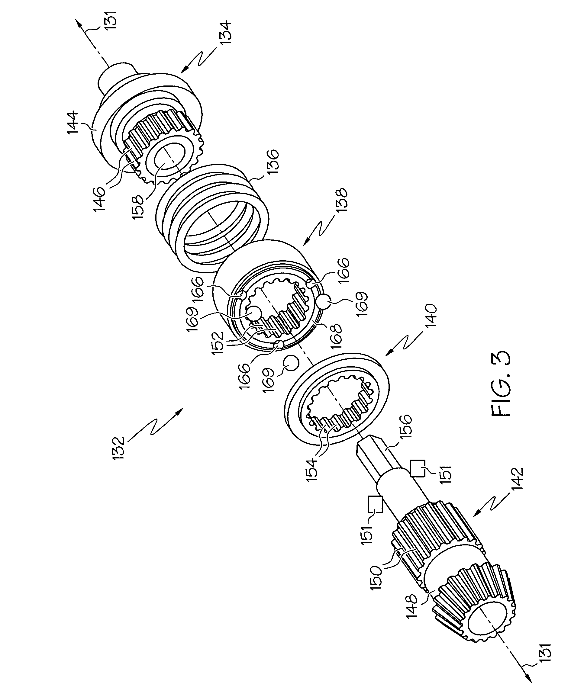
[0019]FIG. 4 illustrates a translating plate or spline 200 having a lubricant retaining feature in accordance with the present invention. Spline 200 (e.g., carbonized steel) comprises a first end section 202, a second end section 204 substantially opposite section 202, and a medial section 206 intermediate sections 202 and 204. Sections 202, 204, and 206 cooperate to form a substantially tubular (e.g., annular) body comprising an outer annular portion and an inner annular portion 210 having an aperture 208 therethrough. Inner annular portion 210 includes a plurality of inwardly-protruding teeth 212 circumferentially spaced around portion 210. Teeth 212 are configured to matingly engage the teeth of a rotatable body disposed within aperture 208 (e.g., teeth 146 of input shaft 134) as described above. Inner annular portion 210 further includes a plurality of root structures 214 that are interspersed with teeth 212. Root structures 214 may be conveniently described as exposed portions ...

second embodiment

[0021]FIG. 5 illustrates a spline 300 in accordance with the present invention. Spline 300 is similar to spline 200 (FIG. 4); i.e., spline 300 includes a first end section 302, a second end section 304, and a medial section 306 disposed between sections 302 and 304. Sections 302, 304, and 306 cooperate to form an annular body having an aperture 308 therethrough and an inner annular portion 310, which comprises a plurality of alternating teeth 312 and root structures 314. Unlike spline 200, however, spline 300 includes a plurality of radially transverse slots 316 between each of teeth 312. Preferably, each slot 316 is disposed within the middle of a different one of root structures 314, and is substantially parallel to the axis about which spline 300 rotates. Slots 316 may assume a variety of shapes and dimensions. Slots 316 should not, however, extend entirely through end section 302 or end section 304 as this would allow lubricant to escape from inner annular portion 310 during the...


PUM


Abstract

A torque limiter for use on an aircraft comprises a drive shaft having a toothed outer portion, an output shaft, and a spline having an aperture therethrough for receiving the toothed portion. The spline is configured to rotationally couple the drive shaft to the output shaft and to rotationally disengage from the output shaft when the torque at the drive shaft exceeds a predetermined torque threshold. The spline comprises an outer annular portion and an inner annular portion configured to receive a lubricant. The inner annular portion comprises a plurality of circumferentially-spaced tooth structures and root structures. At least one of the root structures has at least one slot therein for receiving and retaining the lubricant.

Description

TECHNICAL FIELD[0001]The present invention relates to a torque limiter employed in an aircraft's transcowl actuation system and, more particularly, to a spline including an inner annular portion having one or more lubricant retaining features.BACKGROUND[0002]In spline couplings and other such rotary couplings (e.g., epicycle gear couplings), a drive shaft may be received within a cavity provided through annular plate or spine. In certain systems, the spline may translate with respect to the drive shaft. For example, in a ball ramp torque limiter, the spline may comprise a translating plate having a plurality of inner teeth that engage outer teeth provided about the drive shaft. The spline is spring biased toward a second, non-translating plate that is coupled to an output shaft. When the torque at the drive shaft is below a predetermined threshold, the spline and the non-translating plate abutting engage. The spline and the non-translating plate each include a series of conical pock...

Claims


Application Information

Patent Timeline
Patent Type & Authority Patents(United States)
IPC IPC(8): F16D3/06
CPCF16D3/06F16D7/08Y10T403/7035F16D2300/06F16D2001/103
Inventor BRISTOL, BRENT L.NERI, REMO N.CHAKKERA, KEVIN K.MATHIS, DAVID M.
Owner HONEYWELL INT INC
Why Eureka
Try Eureka