Cutting tool and method of use

a technology of cutting tools and cutting tools, which is applied in the direction of gear teeth, gear sawing accessories, gear-teeth manufacturing apparatus, etc., can solve the problems of high friction and stress at the interface between teeth and material being cut, high temperature and wear rate of teeth, and added cos

Active Publication Date: 2009-03-03
JAMES HARDIE TECH LTD
View PDF40 Cites 9 Cited by
  • Summary
  • Abstract
  • Description
  • Claims
  • Application Information

AI Technical Summary

Problems solved by technology

One problem with this method is the high levels of friction and stress at the interface between the teeth and material being cut.
The high friction causes very high temperatures and wear rates on the teeth.
Consequently, the teeth need to be sharpened regularly; a process that adds cost, increases downtime and ultimately reduces tool life.
While these methods do reduce the wear rate on the tool, the special materials are expensive at the outset and more difficult to overhaul.
Another problem with cutting FRC is that the cellulose fibre in the brittle matrix can be difficult to cut.
Such fluid application is commonly used when cutting metals concrete and stone however is not readily applied to FRC.

Method used


Image

  • Cutting tool and method of use
  • Cutting tool and method of use
  • Cutting tool and method of use

Examples


Embodiment Construction

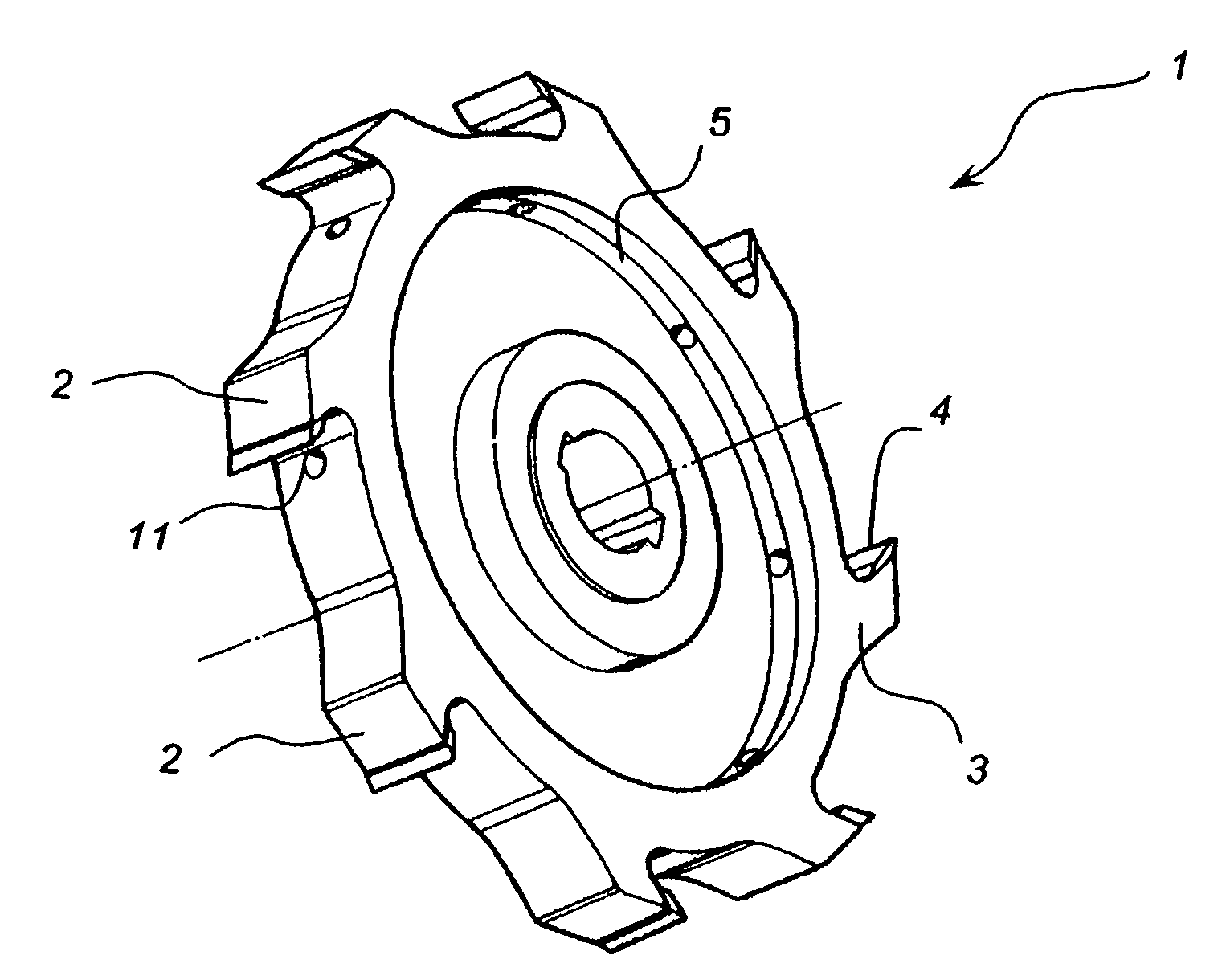
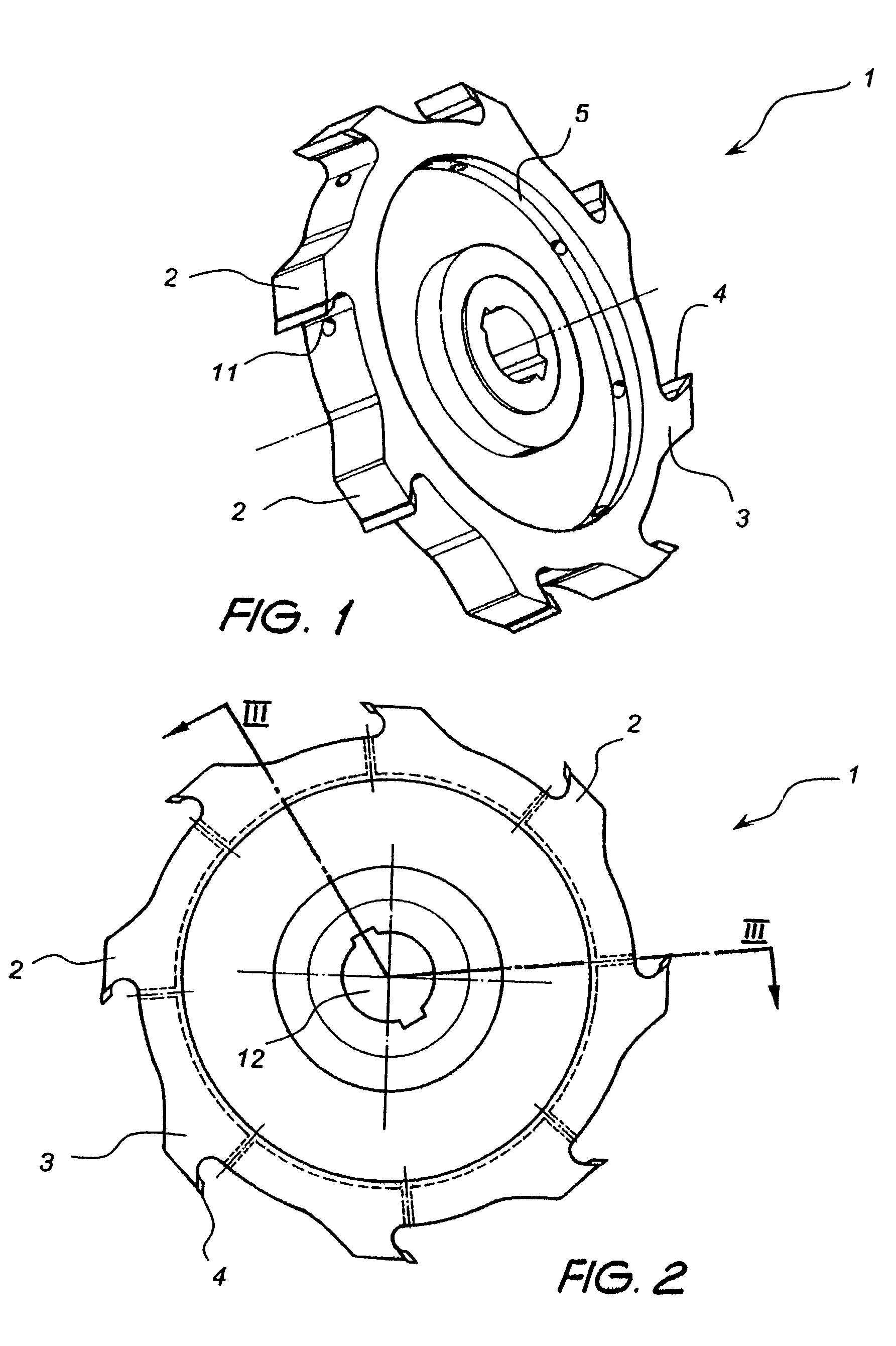
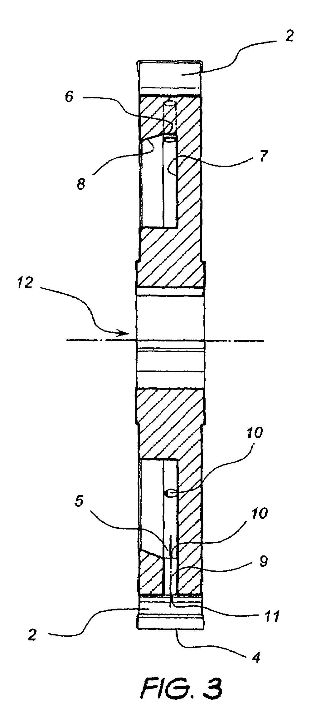
[0027]Referring to the drawings, the cutting tool shown generally as 1, has a disc with a peripheral cutting face. In this embodiment the cutting face includes an array of eight circumferentially spaced teeth 2 for slicing through Fibre Reinforced Concrete (FRC). Each tooth has a wide base 3 at the periphery of the disc and terminates at cutting edge 4.

[0028]The term “cutting” is used herein to describe a number of operations to which the tool of the preferred embodiments may be configured to perform. For instance the disc may be use to slice, route, plane, grind, buff or polish. Accordingly, the cutting face may include any number of teeth shaped to a specific task or grinding or polishing surfaces, without departing from the scope of the invention. These embodiments might also be applied to a tool for performing any of the above operations to any number of base materials, for instance, metal, stone, ceramics, concrete, composites or timber.

[0029]An open circumferential gutter 5 is...


PUM

PropertyMeasurementUnit
rotationaaaaaaaaaa
operational speedaaaaaaaaaa
frictionaaaaaaaaaa

Abstract

The cutting tool shown generally as 1, has a disc with a peripheral cutting face. In this embodiment the cutting face includes an array of eight circumferentially spaced teeth 2. An open circumferential gutter 5 is located inboard of the teeth and is recessed into a lateral face of the disc. Fluid in the gutter drains into the passageways through the respective inlets under the apparent force due to rotation. A fluid passageway 9 runs between the gutter and the base of the each tooth. The fluid is thereby forced through the passageway and out of outlet 11.

Description

PRIORITY INFORMATION[0001]This application claims priority to Australian Application No. 2003906177, filed Nov. 7, 2003, the entirety of which is hereby incorporated by reference.BACKGROUND OF THE INVENTION[0002]1. Field of the Invention[0003]Embodiments of the present invention relate generally to cutting tools, and more particularly to rotating, fluid lubricated cutting tools.[0004]2. Description of the Related Art[0005]As with many building materials, fibre reinforced concrete (FRC) sheeting and piping is cut using a high speed rotating blade cutter. Spinning at high rpm, the disc has a number of peripheral teeth which steadily remove slices of material as the spinning disc is advanced along a cutting path.[0006]One problem with this method is the high levels of friction and stress at the interface between the teeth and material being cut. The high friction causes very high temperatures and wear rates on the teeth. Consequently, the teeth need to be sharpened regularly; a process...

Claims


Application Information

Patent Timeline
Patent Type & Authority Patents(United States)
IPC IPC(8): B26D7/08B23D59/02B23D61/02
CPCB23D59/02B23D61/025Y10T409/304032Y10T407/1906Y10T409/303752Y10T407/14Y10T83/041Y10T83/0443Y10T83/263Y10T83/9329Y10T83/9365
Inventor BRUNTON, GREG
Owner JAMES HARDIE TECH LTD
Why Eureka
Try Eureka