Rate gyroscope and accelerometer multisensor, and method of fabricating same

a multi-sensor, rate technology, applied in the direction of magnetic bodies, magnetic circuit shapes/forms/construction, instruments, etc., can solve the problem of limiting the performance of inertial instruments made by such techniques, and achieve the effect of large angular momentum, higher performance, and use of angular momentum

Inactive Publication Date: 2005-10-27
MILLI SENSOR & ACTUATOR SYST
View PDF2 Cites 10 Cited by
  • Summary
  • Abstract
  • Description
  • Claims
  • Application Information

AI Technical Summary

Benefits of technology

[0005] It is therefore an object of this invention to develop techniques by which useful angular momentum can be accomplished in a spinning wheel multisensor instrument. This objective is accomplished by fabricating the device by a process termed “millimachining.” Millimachining is a fabrication approach developed from a merging of traditional machining technologies and the emerging micro-machining technology, applied to devices in the size range between macro and micro. Millimachined gyroscopes can have larger angular momentum and are thus expected to realize higher performance than micro gyroscopes fabricated with the now widespread MEMS technologies. Millimachined devices can also be expected to be less expensive and more reliable than conventionally fabricated macro-sized instruments because they can take advantage of the economy and reproducibility of batch processing and dispense with most of the expensive, time consuming and unreliable hands-on human labor.
[0006] This invention features in one embodiment a process for fabricating a rate gyroscope and accelerometer multisensor having an inner magnetically-suspended spinning wheel rotor, with outer stator portions adjacent both faces of the rotor. The high-speed rotation of the wheel, which can be somewhat smaller than a dime, can produce an angular momentum much larger than that of the Coriolis force based MEMS gyroscopes now receiving intensive development, and is expected to provide considerably higher performance than currently available from this class of instrument. Two axes of angular rate information and three axes of acceleration information are provided by the control loops that center the wheel within the case. Thus, two such magnetically suspended spinning wheel devices can be used to implement a complete IMU, and can also provide redundancy in four of the six degrees of freedom.

Problems solved by technology

The angular momentums that can be developed with the micro vibrating members of Coriolis force gyroscopes limit the performance of inertial instruments made by such techniques.

Method used


Image

  • Rate gyroscope and accelerometer multisensor, and method of fabricating same
  • Rate gyroscope and accelerometer multisensor, and method of fabricating same
  • Rate gyroscope and accelerometer multisensor, and method of fabricating same

Examples


Embodiment Construction

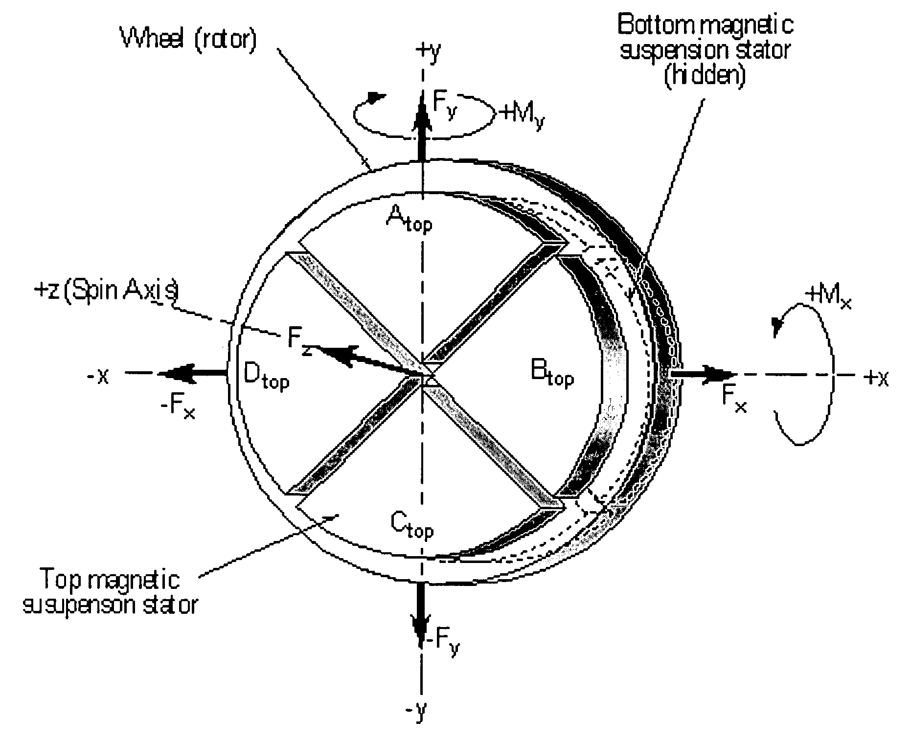
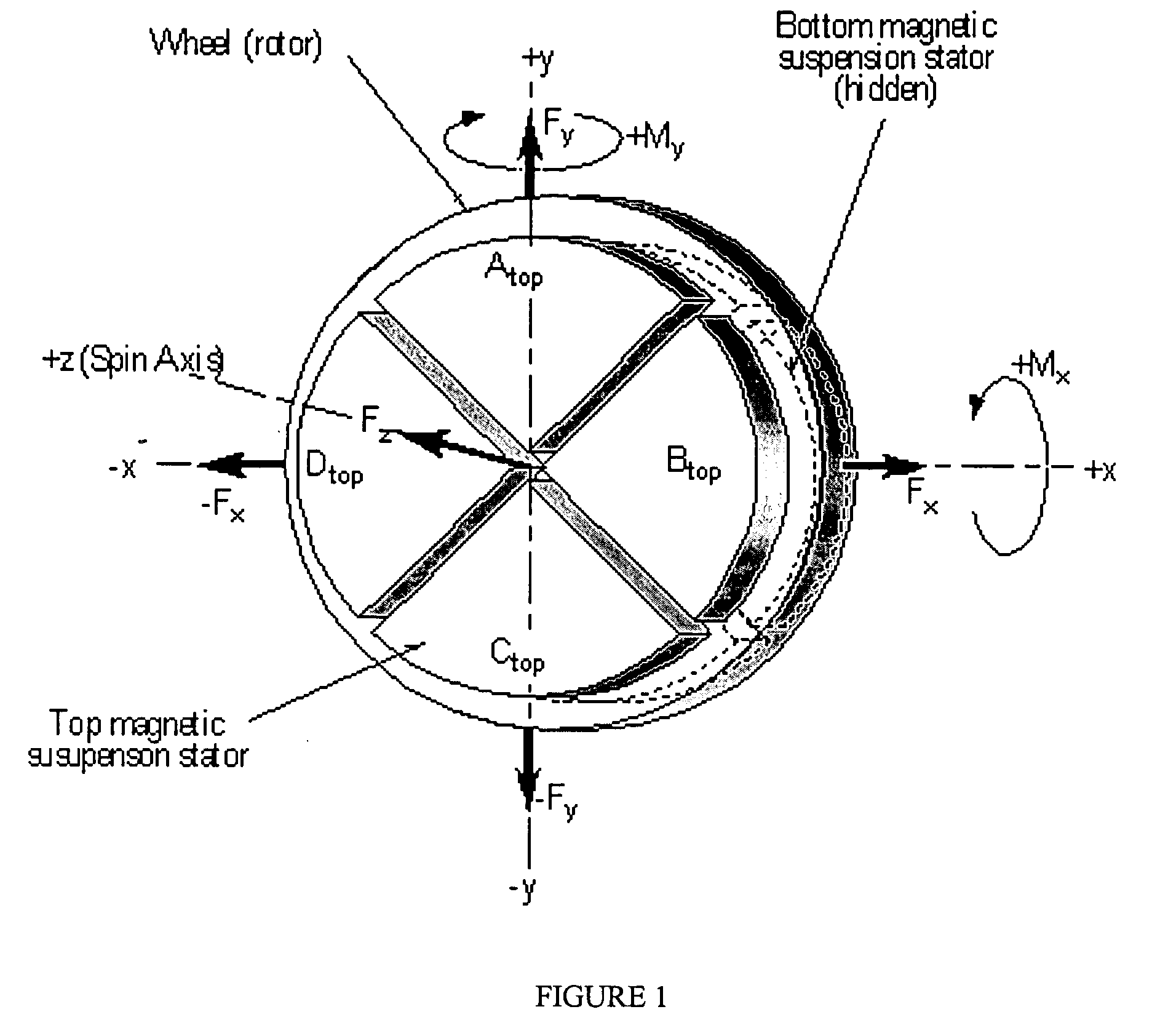
[0021] The conceptual design of the preferred embodiment of the invention is disclosed in U.S. Pat. No. 5,959,382, the entire disclosure of which is incorporated herein by reference. The design is schematically depicted in FIG. 1. The control logic for the design is summarized in Table 1.

TABLE 1MAGNETIC SUSPENSION CONTROL LOGICSector+Fx−Fx+Fy−Fy+Fz−Fz+Mx−M+My−MyAtop+Δi−Δi+Δi−Δi+Δi−ΔiBtop+Δi−Δi+Δi−Δi+Δi−ΔiCtop−Δi+Δi+Δi−Δi−Δi+ΔiDtop−Δi+Δi+Δi−Δi+Δi−ΔiAbottom+Δi−Δi−Δi+Δi−Δi+ΔiBbottom+Δi−Δi−Δi+Δi+Δi−ΔiCbottom−Δi+Δi−Δi+Δi+Δi−ΔiDbottom−Δi+Δi−Δi+Δi−Δi+Δi

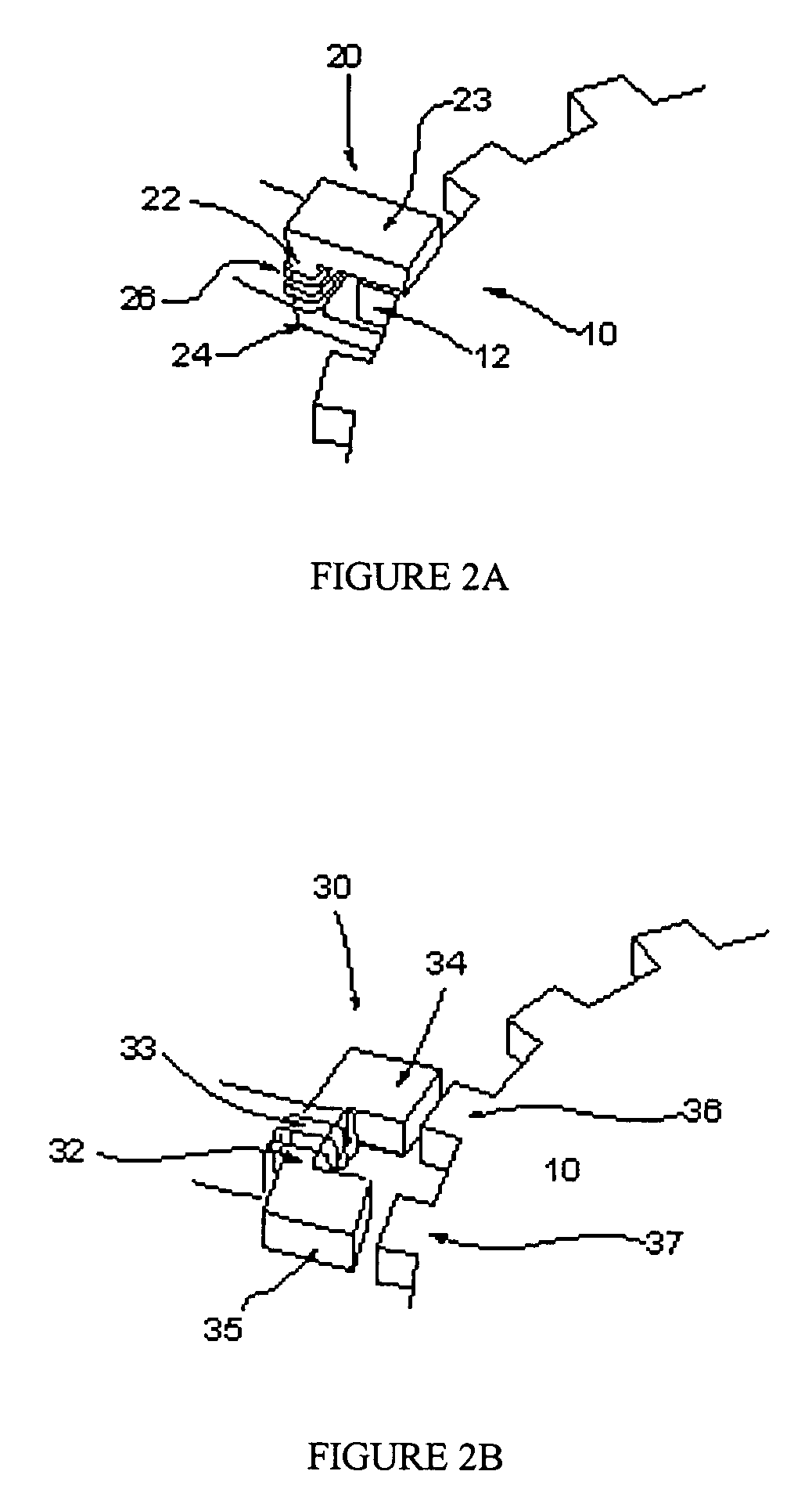
[0022] The design herein encompasses two different variable reluctance motor designs. The two designs of spin motors for the magnetically suspended spinning wheel gyroscope are termed: radial air gap (FIG. 2A) and axial air gap (FIG. 2B). Of the two, the axial air gap design lends itself well to the same fabrication approach that can be used to form the magnetic suspension components.

[0023] Axial air gap design 20, FIG. 2A, comprises coil...


PUM

PropertyMeasurementUnit
degrees of freedomaaaaaaaaaa
magneticaaaaaaaaaa
thicknessaaaaaaaaaa

Abstract

A rate gyroscope and accelerometer multisensor, and a process for fabricating the device. The device has an inner magnetically-suspended spinning wheel rotor, with outer stator portions adjacent both faces of the rotor. In one embodiment of the process, three substrates of magnetic material are provided. A first substrate is used to form the portion comprising the rotor. The other two substrates are used to form the outer stator portions. A series of spaced concentric grooves are formed in the central region of both faces of the first substrate. Outside of the grooves on both faces of the first substrate a series of spaced spiral grooves are formed. A hole is placed at the center of the spiral grooves, and filled with magnetic material. A conductor is then deposited into the spiral grooves. A central wheel is formed, the wheel carrying the spaced concentric grooves and defining along its edge a series of spaced teeth. A series of spaced serpentine grooves are formed on one active face of each of the other two substrates. On the same face, a series of generally radial grooves are formed. A conductor is then deposited into the serpentine grooves, and a magnetic material is deposited into the generally radial grooves. The active faces of the two outer substrates are then bonded against the first substrate such that the outer end of each magnetic path overlays a filled hole in the first substrate, to create the stator of an axial air gap reluctance motor.

Description

CROSS REFERENCE TO RELATED APPLICATION [0001] This application claims priority of Provisional application Ser. No. 60 / 565,062, filed on Apr. 23, 2004.FIELD OF THE INVENTION [0002] This invention relates to a rate gyroscope and accelerometer multisensor, and a process for fabricating the device. BACKGROUND OF THE INVENTION [0003] An instrument capable of being used as a rate gyroscope and accelerometer multisensor is conceptually described in U.S. Pat. No. 5,959,382. The device can be used to measure rotation rate about two orthogonal axes, and accelerations along all three axes. Two such devices thus can be configured as a 6 DOF inertial instrument. [0004] In order to make this multisensor a commercially viable product, it is necessary to use mass production techniques. However, currently used MEMS techniques are adapted for production of micro instruments. The angular momentums that can be developed with the micro vibrating members of Coriolis force gyroscopes limit the performance...

Claims


Application Information

Patent Timeline
Patent Type & Authority Applications(United States)
IPC IPC(8): G01C19/24G01P15/18H01L21/00H02K7/09H02K19/10
CPCG01C19/24G01P15/18H02K7/09H02K19/103Y10T29/49167Y10T29/49048Y10T29/49155Y10T29/4902Y10T29/49156
Inventor DAUWALTER, CHARLES R.CARDARELLI, DONATOGREIFF, PAUL
Owner MILLI SENSOR & ACTUATOR SYST
Why Eureka
Try Eureka