

Image processing device and method
a technology of image processing and image, applied in the field of image processing device and method, can solve the problem of unoptimized macro block size of 1616 pixels
Active Publication Date: 2012-04-19
SONY CORP
View PDF10 Cites 49 Cited by
- Summary
- Abstract
- Description
- Claims
- Application Information
AI Technical Summary
Benefits of technology
Problems solved by technology
However, a macro block size of 16×16 pixels is not optimal for large image frames such as UHD (Ultra High Definition; 4000×2000 pixels) which will be handled by next-generation encoding methods.
Method used
View moreImage
Smart ImageViewing Examples

Examples
first embodiment (
1. First Embodiment (neighboring pixel interpolation filter switching: example of intra prediction)
second embodiment (
2. Second Embodiment (neighboring pixel interpolation filter switching: example of second order prediction)
third embodiment (
3. Third Embodiment (neighboring pixel interpolation filter on / off control: example of intra prediction)
Login to View More PUM
 Abstract
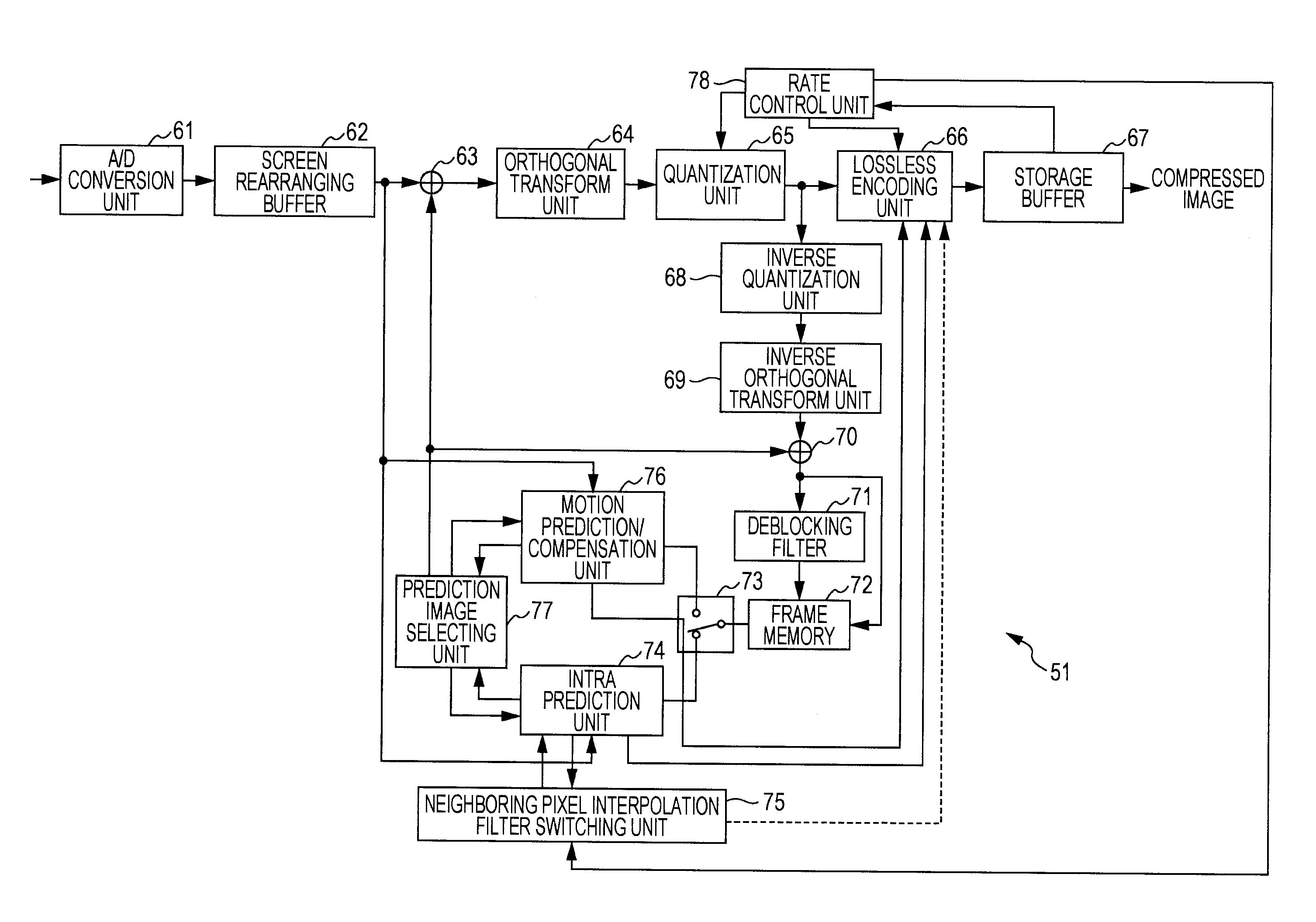
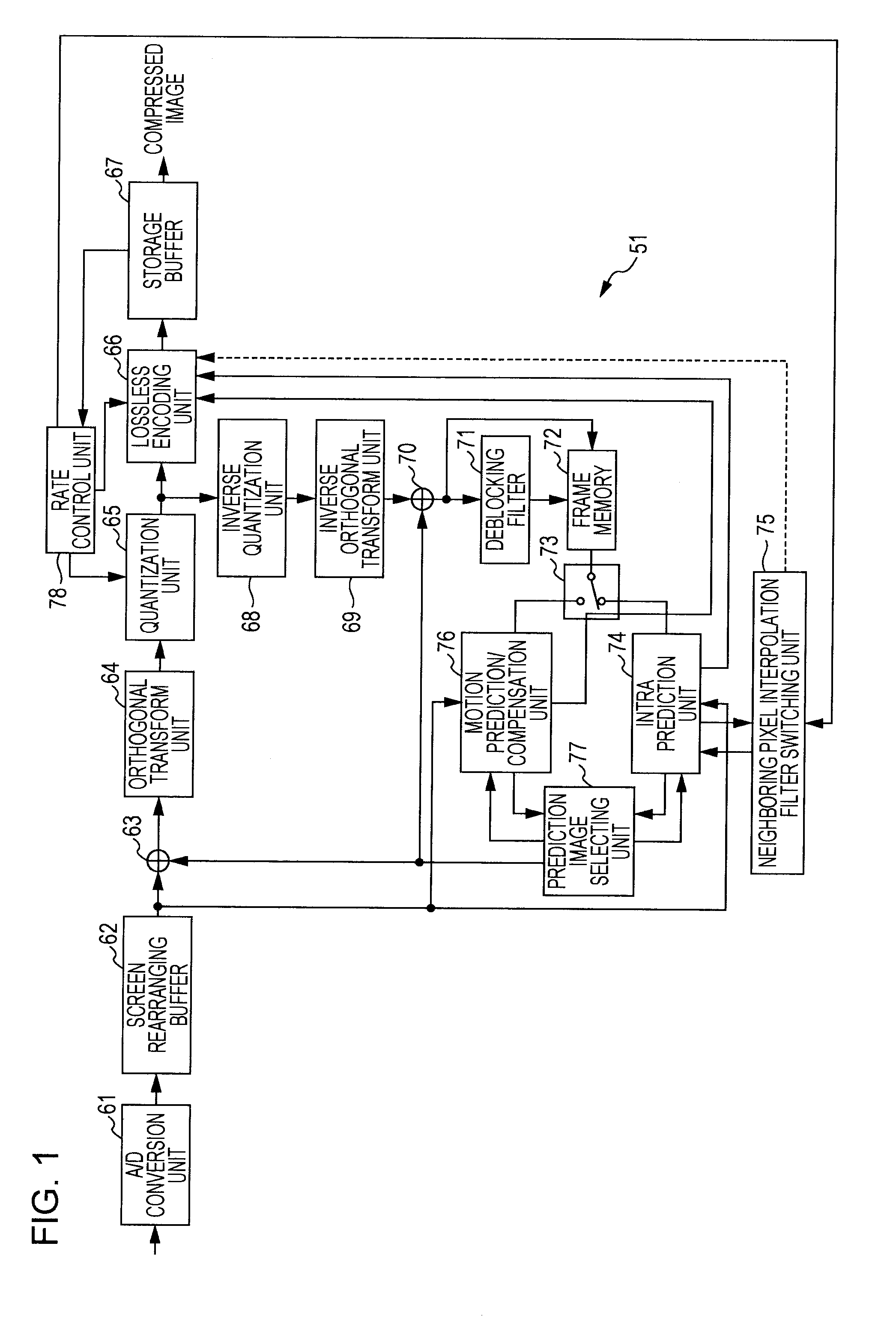
The present invention relates to an image processing device and method enabling noise removal to be performed according to images and bit rates.A low-pass filter setting unit 93 sets, from filter coefficients stored in a built-in filter coefficient memory 94, a filter coefficient corresponding to intra prediction mode information and a quantization parameter. A neighboring image setting unit 81 uses the filter coefficient set by the low-pass filter setting unit 93 to subject neighboring pixel values of a current block from frame memory 72 to filtering processing. A prediction image generating unit 82 performs intra prediction using the neighboring pixel values subjected to filtering processing, from the neighboring image setting unit 81, and generates a prediction image. The present invention can be applied to an image encoding device which encodes with the H.264 / AVC format, for example.
Description
TECHNICAL FIELD[0001]The present invention relates to an image processing device and method, and specifically relates to an image processing device and method which enable prediction efficiency to be improved.BACKGROUND ART[0002]In recent years, there have come into widespread use devices which subject an image to compression encoding by employing an encoding format for handling image information as digital signals, and taking advantage of redundancy peculiar to the image information with transmission and storage of high effective information taken as an object at that time to compress the image by orthogonal transform such as discrete cosine transform or the like and motion compensation. Examples of this encoding method include MPEG (Moving Picture Experts Group) and so forth.[0003]In particular, MPEG2 (ISO / IEC 13818-2) is defined as a general-purpose image encoding format, and is a standard encompassing both of interlaced scanning images and sequential-scanning images, and standar...
Claims
Login to View More Application Information
Patent Timeline
 Patent Type & AuthorityApplications(United States)
IPC IPC(8): G06K9/36H04N19/50H04N19/117H04N19/12H04N19/134H04N19/136H04N19/146H04N19/147H04N19/152H04N19/154H04N19/159H04N19/176H04N19/19H04N19/196H04N19/423H04N19/46H04N19/503H04N19/51H04N19/513H04N19/593H04N19/61H04N19/625H04N19/70H04N19/80H04N19/91
CPCG06T9/004H04N19/593H04N19/50H04N19/159H04N19/176H04N19/86H04N19/11H04N19/117H04N19/80H04N19/82H04N19/46H04N19/103H04N19/85G06T1/00G06T9/00
InventorSATO, KAZUSHI
OwnerSONY CORP