Cross connectors

a technology of cross-connectors and connectors, which is applied in the field of medical devices, can solve the problems of most conventional connectors not being able to protect, surgeons may have a difficult time in adjusting these connectors, and most conventional connectors lack pre-fixation flexibility

Inactive Publication Date: 2012-04-19
SPINOFIX
View PDF2 Cites 77 Cited by
  • Summary
  • Abstract
  • Description
  • Claims
  • Application Information

AI Technical Summary

Benefits of technology

[0011]In another embodiment, the present invention may provide a cross connector for stabilizing and protecting one or more fixation levels of spinal bone segments. The cross connector may include a first connector including a first pair of arms and a first joint positioned between the first pair of arms, the first joint having a first platform having a first bell-shaped ridge connecting the first pair of arms to form a first contiguous arc along a first reference plane, the first bell-shaped ridge furnished with a first convex edge, and a first bracket formed on the first platform, the first bracket having a first vertical concave contour substantially parallel to the first reference plane, and a first horizontal concave contour intersecting the first vertical concave contour and substantially perpendicular to the first reference plane, a second connector including a second pair of arms and a second joint positioned between the second pair of arms, the second joint having a complementary configuration with respect to the first joint, the second joint connecting the second pair of arms to form a second contiguous arc along a second reference plane intersecting the first reference plane alone a center axis, and a pivoting means for pivoting the first connector against the second connector along the center axis, thereby allowing a limited range of angular movement between the first pair of arms and the second pair of arms.
[0012]In yet

Problems solved by technology

For example, some conventional connectors may be made of flat and straight arms, such that surgeons may have a difficult time in adjusting these connectors to fit the contour the of patient's spinal bone segments.
Accordingly, the implantation of these conventional connectors may require the removal of the patient's spinous process from one or more spinal bone segments because they may not be adap

Method used


Image

  • Cross connectors
  • Cross connectors
  • Cross connectors

Examples


Embodiment Construction

[0076]Apparatus, systems and methods that implement the embodiment of the various features of the present invention will now be described with reference to the drawings. The drawings and the associated descriptions are provided to illustrate some embodiments of the present invention and not to limit the scope of the present invention. Throughout the drawings, reference numbers are re-used to indicate correspondence between reference elements. In addition, the first digit of each reference number indicates the figure in which the element first appears.

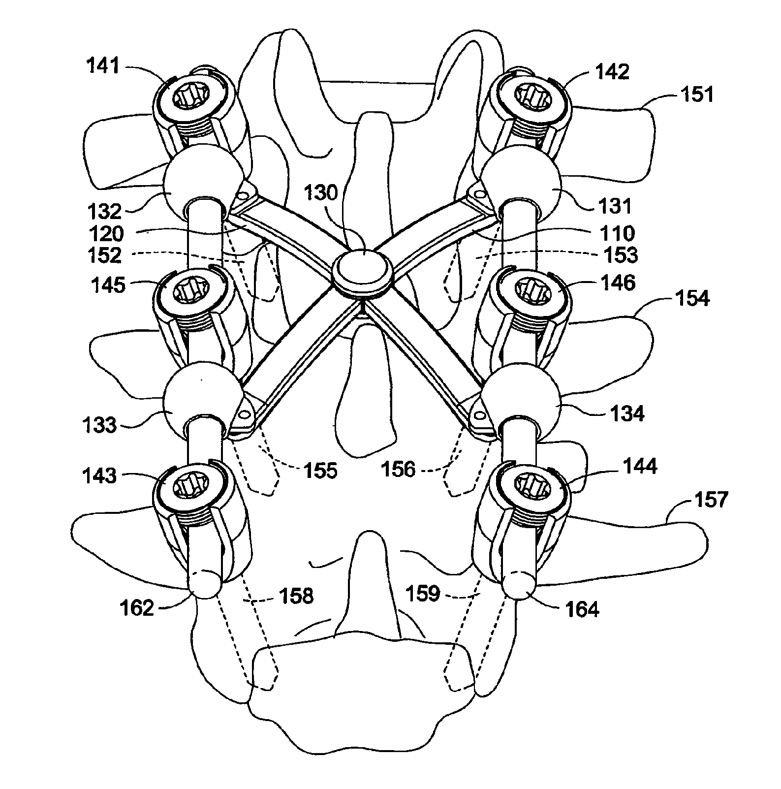
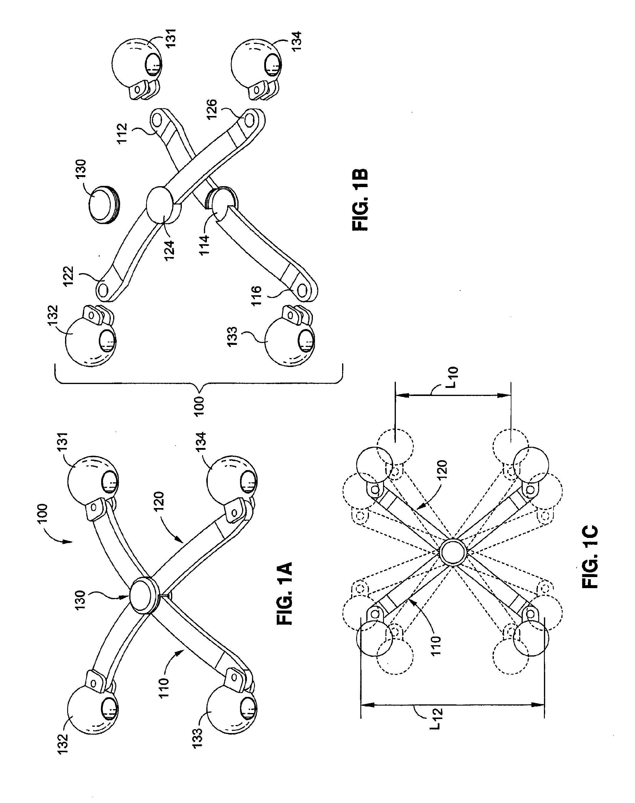
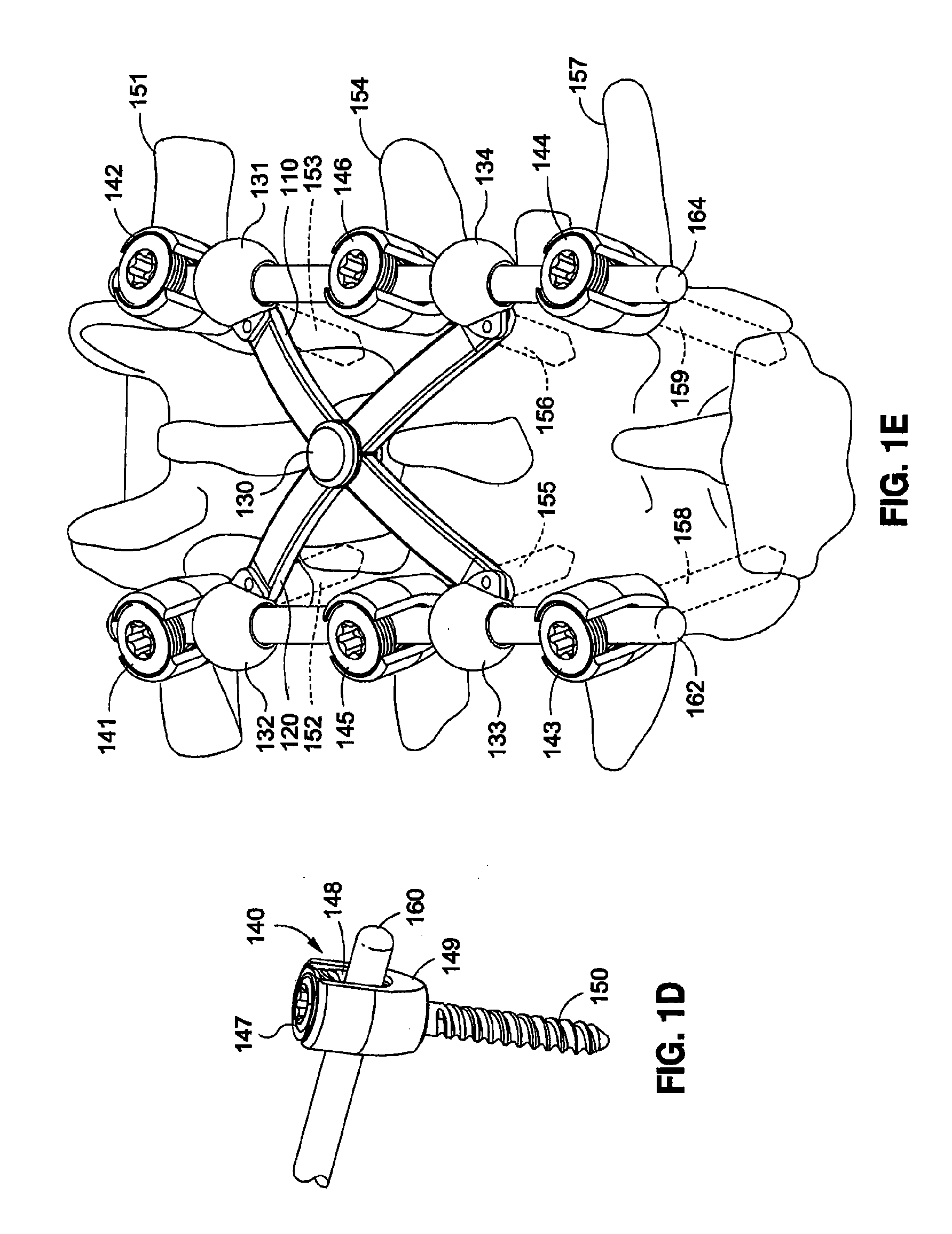
[0077]FIGS. 1A-1C show various views of a Real-X cross connector (RXCC) 100 according to an embodiment of the present invention. As shown in FIG. 1A, the RXCC 100 may include a first elongated member (first arm) 110, a second elongated member (second arm) 120, a fulcrum member 130, and four connecting devices 131, 132, 133, and 134. Generally, as shown in FIG. 1B, the first and second elongated members 110 and 120 may have first ends 11...


PUM


Abstract

The present invention may provide various improvements over conventional cross connectors. For example, the present invention may provide various types of Real-X cross connectors, which may have an arch shape X-bridge that curves above the spinal bone segments of the patient. As such, the Real-X cross connectors may be more adaptive to the patient's spinal provide and provide better protect for the patient's the spinal bone segments. Moreover, the Real-X cross connectors may incorporate a complementary pivot joint configuration for smoothening the stress distribution and reducing the stress concentration around the center of the arch shape X-bridge. Advantageously, the complementary pivot joint configuration may enhance the rigidity and stability of the Real-X cross connectors.

Description

RELATED APPLICATIONS[0001]This application is a continuation-in-part of application Ser. No. 12 / 962,996, entitled “CROSS CONNECTORS,” filed on Dec. 8, 2010, which is a continuation-in-part of application Ser. No. 12 / 906,991, entitled “CROSS CONNECTORS,” filed on Oct. 18, 2010. The aforementioned related applications are assigned to the assignee hereof and hereby expressly incorporated by reference herein.BACKGROUND[0002]1. Field[0003]The present invention relates generally to the field of medical devices used in posterior spinal fixation surgery, and more particularly to cross connectors.[0004]2. Description of the Related Art[0005]Posterior spinal fixation surgery is a common procedure for patients who suffer from severe spinal conditions, such as spinal displacement, spinal instability, spinal degeneration, and / or spinal stenosis. Among other therapeutic goals, a successful posterior spinal fixation surgery may lead to the stabilization and fusion of several spinal bone segments o...

Claims


Application Information

Patent Timeline
IPC IPC(8): A61B17/70
CPCA61B17/7004A61B17/7005A61B17/701A61B17/7014A61B17/8042A61B17/7037A61B17/7049A61B17/7052A61B17/7032
Inventor NIHALANI, RAJ
Owner SPINOFIX
Why Eureka
Try Eureka