Pipe joint structure

Inactive Publication Date: 2012-04-26
SING ENTERPRISES CO LTD
View PDF0 Cites 19 Cited by
  • Summary
  • Abstract
  • Description
  • Claims
  • Application Information

AI Technical Summary

Benefits of technology

[0006]Preferably, the resilient ring is provided with a n

Problems solved by technology

The connection pipe is threadedly connected to the pipe joint, which consumes a lot of time and labor.
The traditional connection way w

Method used


Image

  • Pipe joint structure
  • Pipe joint structure
  • Pipe joint structure

Examples


Embodiment Construction

[0013]Embodiments of the present invention will now be described, by way of example only, with reference to the accompanying drawings.

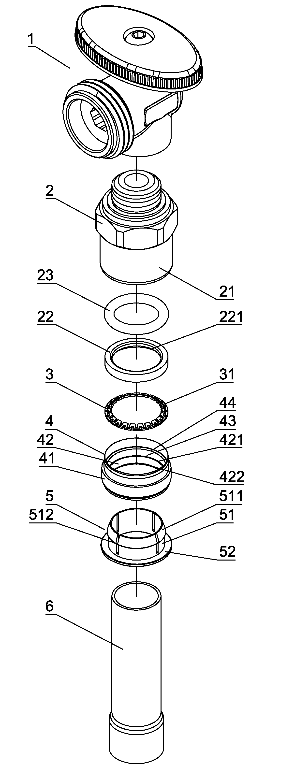
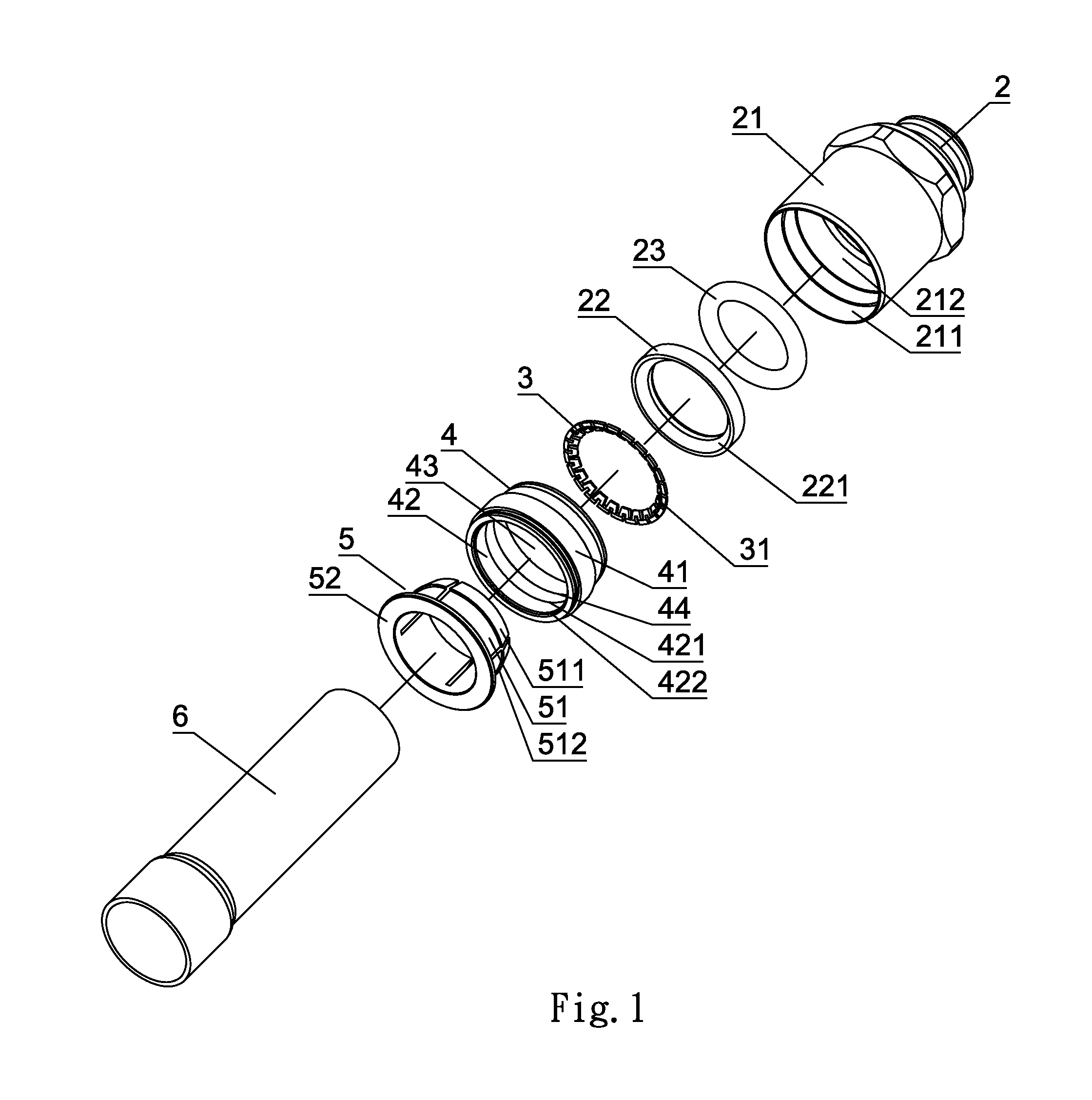
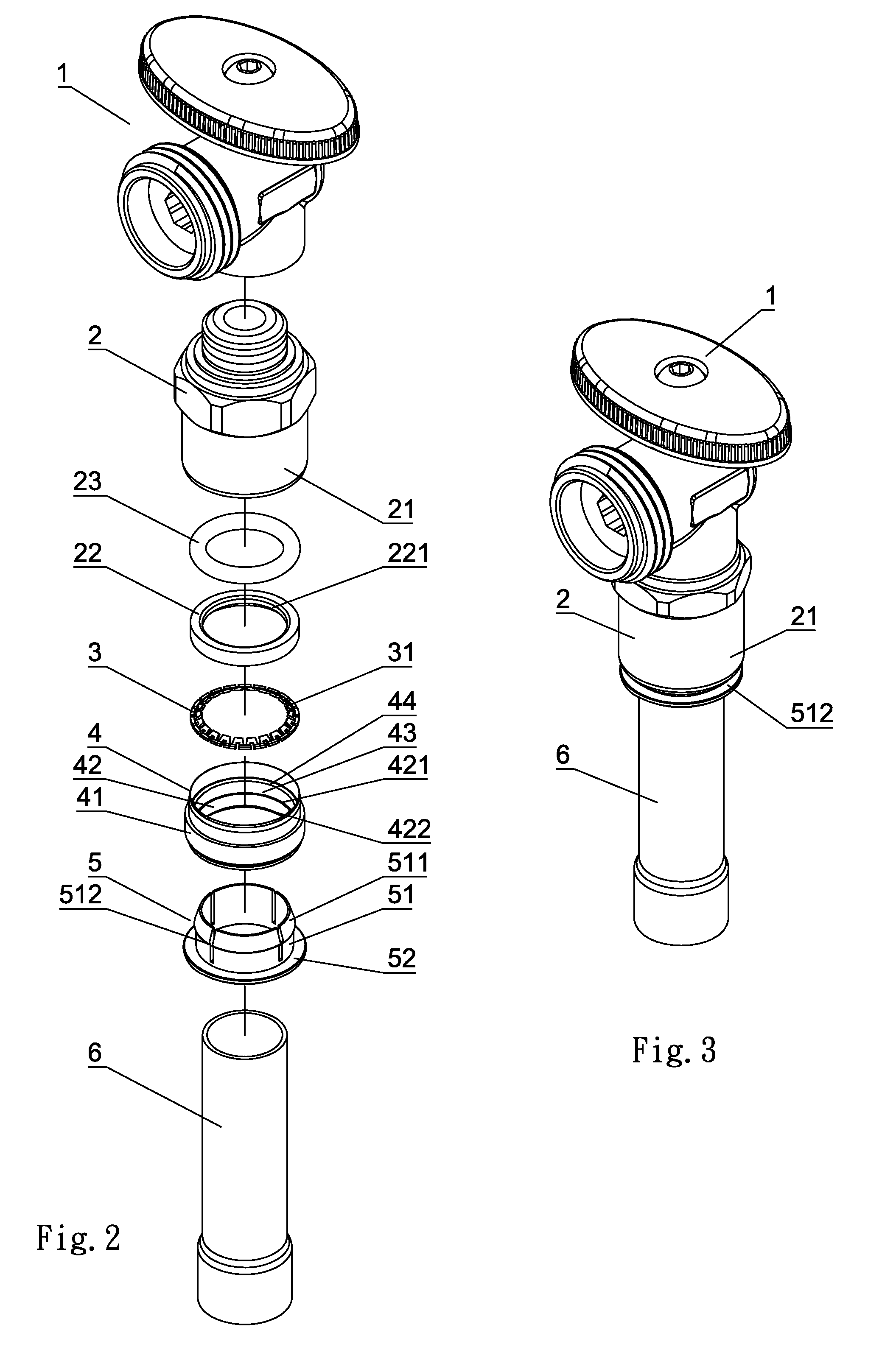
[0014]As shown in FIG. 1 through FIG. 4, a pipe joint structure according to a preferred embodiment of the present invention comprises a pipe joint 2 coupled to an upright valve 1, a resilient ring 3, a connection cylinder 4 and an inner sleeve 5.

[0015]The pipe joint 2 includes a receiving pipe 21, a concave recess 211 disposed at one end of the receiving pipe 21, a first chamber 212 above the concave recess, a positioning ring 22 and a seal ring 23 received in the first chamber 212. The positioning ring 22 has an inner limit inclined surface 221.

[0016]The resilient ring 3 includes a plurality of fastening talons 31 which are slightly slanted upward for one-way insertion of a connection pipe 6 so as to engage with the outer wall of the connection pipe 6. The resilient ring 3 is clamped between the positioning ring 22 and the inner sleeve 5.

[0017]The c...


PUM


Abstract

A pipe joint structure for an upright valve includes a pipe joint, a resilient ring, a connection cylinder and an inner sleeve. The pipe joint includes a first chamber to receive a positioning ring and a seal ring. The resilient ring, the connection cylinder and the inner sleeve are inserted in the pipe joint in sequence. When a connection pipe is inserted in the pipe joint, the connection pipe will be inserted in a one-way direction and fastened by fastening talons of the resilient ring. To disengage the connection pipe, top push flanges of resilient claws of the inner sleeve are pushed to an inner limit inclined surface of the positioning ring to disengage the connection pipe from the fastening talons, such that the connection pipe can be pulled out. The present invention provides a quick connection and can prevent the connection pipe from being pulled out unexpectedly.

Description

BACKGROUND OF THE INVENTION[0001]1. Field of the Invention[0002]The present invention relates to a pipe joint structure.[0003]2. Description of the Prior Art[0004]A conventional upright valve includes a pipe joint under the upright valve. The pipe joint has a threaded pipe to connect a connection pipe. The connection pipe is threadedly connected to the pipe joint, which consumes a lot of time and labor. The connection of the connection pipe and joint pipe cannot be done outside and then connected to the upright valve, which must be coupled separately. The traditional connection way wastes a lot of time and manpower. Besides, in this connection way, the joint between pipe joint and the connection pipe may leak water.SUMMARY OF THE INVENTION[0005]The primary object of the present invention is to provide a pipe joint structure for an upright valve. The pipe joint structure comprises a pipe joint, a resilient ring, a connection cylinder and an inner sleeve. The pipe joint includes a rec...

Claims


Application Information

Patent Timeline
IPC IPC(8): F16L55/00
CPCF16L37/091F16L37/0915
Inventor CHANG, YEO-SHANCHANG, WEN-SHAN
Owner SING ENTERPRISES CO LTD
Why Eureka
Try Eureka