

Biosensor device for sensing amphipathic analytes
a biosensor and amphipathic analyte technology, applied in the field of sensing elements and devices, can solve the problems of affecting human health, requiring complex sample handling, and slow turnaround time (>1 hour)
- Summary
- Abstract
- Description
- Claims
- Application Information
AI Technical Summary
Benefits of technology
Problems solved by technology
Method used
Image


Examples
example 1
[0047]Acrylodan-labeled fatty acid binding protein was crosslinked to the PEG-based hydrogel backbone molecule as depicted in FIG. 2B. A 1 mg aliquot of lyophilized acrylodan-labeled fatty acid binding protein was dissolved in 550 μL of 1×PBS buffer (pH 7.4) to produce a 120 μM solution. A 60 mM solution of acryloyl-PEG-NHS (APS; MW-3400 Da) was produced in 0.1 M MES buffer (pH 6.3). The protein and PEG solution were mixed at a 5:1 protein:PEG ratio, and allowed to react at room temperature for 2 hours. The reaction mixture was then incubated at 4° C. overnight. PEGylated acrylodan-labeled fatty acid binding protein was purified from un-reacted PEG reagent by using a NAP-10 column (Amersham Biosciences, Piscataway, N.J.). PEGylation of acrylodan-labeled fatty acid binding protein was demonstrated by standard PAGE electrophoresis on a BioRad 4-15% acrylamide gradient gel (120V, 45 min). The gel was stained using a SilverQuest silver staining kit from Invitrogen (Madison, Wis.).
example 2
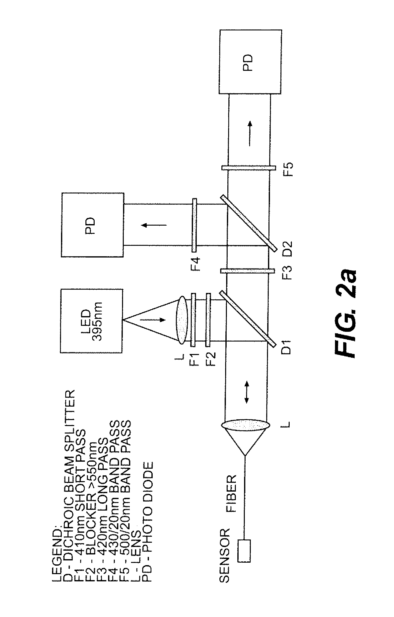
[0048]Sensor Fabrication. Fiber optic-needle sensors were assembled by depositing a small drop of non-fluorescing glue roughly 20 mm from the tip of an optical fiber, then sliding the fiber through the shaft of an 18-gauge needle until the fiber optic tip was located in the center of the needle bevel. The glue was allowed to cure for 15 minutes before additional glue was added to secure the base of the needle to the optical fiber. Stability of the sensor was assessed by vigorous shaking. The sensors were then taped or otherwise affixed to a solid support such as cardboard. 500 μL microcentrifuge tubes were attached to the solid support such that the tips of the needles rested against the bottom of the tubes. After mixing, prepolymer solution was added to the tubes (typically 40 μL each) and allowed to cure for 30-60 minutes. To form the hydrogel matrix, the prepolymer formulation was optimized for maximum stability and fluorescence. After mixing the solution, adding APS last, 40 μL ...
example 3
[0049]In one embodiment, the basic formulation of the polymeric matrix in the absence of co-monomer was as follows. 39.6 μL of PBS buffer was mixed with 42 μL of a 60% PEGDMA (w / v) solution and 1.2 μL of a 25% (v / v) TEMED solution. 36 μL PEGylated acrylodan-labeled fatty acid binding protein was then added to the mixture and the solution was vortexed briefly. After adding 1.2 μL 10% (w / v) APS, the solution was again vortexed briefly. Polymeric matrix compositions containing a co-monomer component contained 25 mol % co-monomer with respect to PEG content. All formulations were mixed as described above. Individual formulations are given below with each separate co-monomer used. When the co-monomer is 2-hydroxy-3-methacryloxypropyl trimethyl ammonium chloride (HMATMAC): 38.7 μL PBS buffer, 42 μL 60% PEGDMA (w / v) in water, 36 μL PEGylated acrylodan-labeled fatty acid binding protein (˜100 μM), 1.2 μL APS (10% w / v), 1.2 μL TEMED (v / v), 0.9 μL HMATMAC (note: this formulation contained onl...
PUM
 Abstract
Description
Claims
Application Information