Vibrating actuator assembly

a technology of actuators and actuator parts, applied in piezoelectric/electrostrictive/magnetostrictive devices, piezoelectric/electrostriction/magnetostriction machines, electrical apparatus, etc., can solve the problems of high power consumption, complex structure increased volume of lens driving devices, so as to reduce noise and vibration generation

Active Publication Date: 2012-05-03
SAMSUNG ELECTRONICS CO LTD
View PDF10 Cites 2 Cited by
  • Summary
  • Abstract
  • Description
  • Claims
  • Application Information

AI Technical Summary

Benefits of technology

[0009]Embodiments can provide a vibrating actuator assembly, whereby generation of noise and vibration can be reduced.

Problems solved by technology

In this case, since a reduction gear and a cam are used to change the rotation of the stepping motor into a rectilinear motion, the volume of the lens driving device may increase, and a structure of the lens driving device may be complex.
Also, during a normal rotation or reverse rotation, a stepping error may be generated, power consumption may be high, and high current and heat may be generated due to backlash.
However, since a conventional optical system including such a piezoelectric device also includes elements, such as a gear or a cam, to change a motion of the piezoelectric device into driving power for moving lenses, the conventional optical system may have a complex structure, and accurate position control may be difficult due to a moving error between the elements.

Method used


Image

  • Vibrating actuator assembly
  • Vibrating actuator assembly
  • Vibrating actuator assembly

Examples


Embodiment Construction

[0036]Hereinafter, structures and operations of vibrating actuator assemblies according to embodiments will be described more fully with reference to the accompanying drawings.

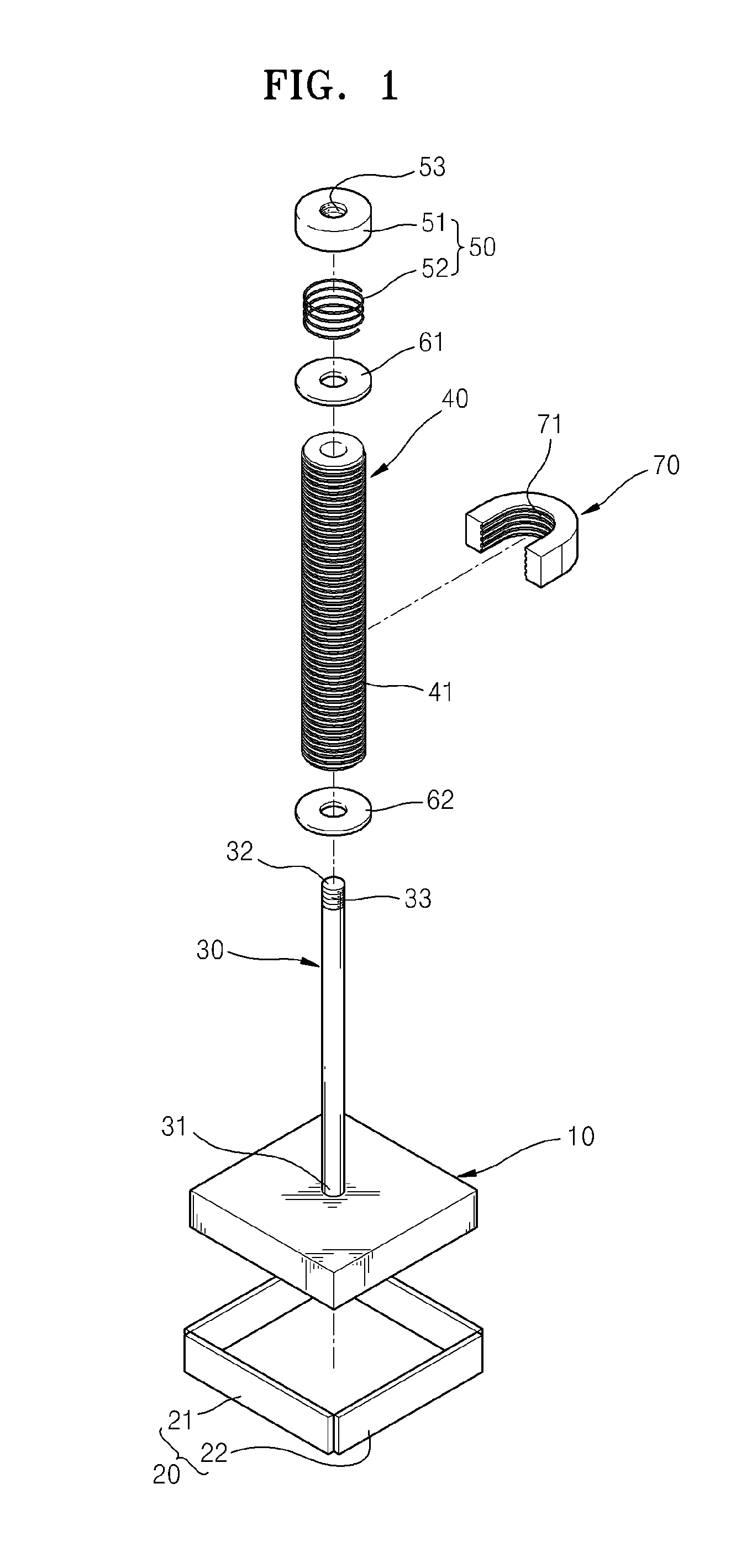
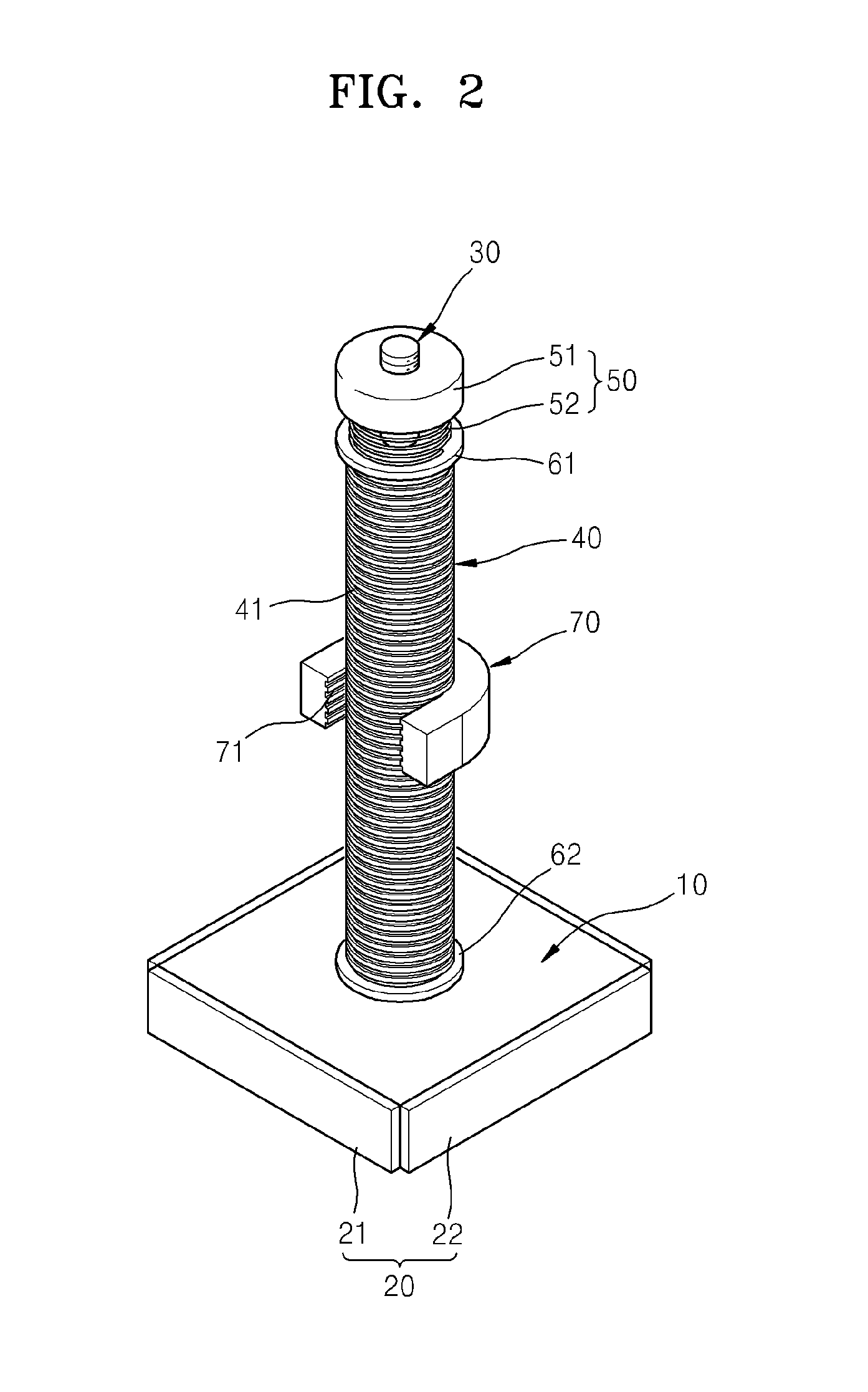
[0037]FIG. 1 is an exploded perspective view illustrating a vibrating actuator assembly according to an embodiment, and FIG. 2 is a perspective view illustrating an assembled state of the vibrating actuator assembly of FIG. 1.

[0038]The vibrating actuator assembly of FIGS. 1 and 2 can include a diaphragm 10, a vibrator 20 that can vibrate the diaphragm 10, a vibration shaft 30 that can have one end 31 connected to the diaphragm 10, a rotor 40 that can be disposed on an outer side of the vibration shaft 30 to be moveable, and an elastic presser 50 that can be installed at another end 32 of the vibration shaft 30 to press the rotor 40.

[0039]The vibrator 20 can be disposed at a side of the diaphragm 10 and can vibrate when an electric signal is applied thereto. When the vibrator 20 vibrates, the diaphragm 10 can b...


PUM


Abstract

A vibrating actuator assembly includes a diaphragm, at least one vibrator at the diaphragm and that vibrates when an electric signal is applied thereto, a vibration shaft having one end connected to the diaphragm, a rotor on an outer side of the vibration shaft to contact an outer surface of the vibration shaft and that moves by vibration of the vibration shaft, and an elastic presser at another end of the vibration shaft and that elastically presses the rotor toward the diaphragm.

Description

CROSS-REFERENCE TO RELATED PATENT APPLICATION[0001]This application claims the priority benefit of Korean Patent Application No. 10-2010-0105382, filed on Oct. 27, 2010, in the Korean Intellectual Property Office, the entire disclosure of which is incorporated herein by reference.BACKGROUND[0002]1. Field of the Invention[0003]Embodiments relate to a vibrating actuator assembly, and more particularly, to a vibrating actuator assembly, whereby generation of noise and vibration is reduced, strong driving power is generated by using a compact structure, and precise position control is possible.[0004]2. Description of the Related Art[0005]An optical system having optical elements, such as lenses, includes a lens driving device to move the lenses. The lens driving device moves the lenses to change a relative distance between them, thereby realizing a zooming function or an auto focusing function.[0006]The lens driving device may include a driving unit such as a stepping motor. In this cas...

Claims


Application Information

Patent Timeline
Patent Type & Authority Applications(United States)
IPC IPC(8): H02N2/12
CPCH02N2/105H02N2/126
Inventor JANG, CHEOL-EUNMOON, CHAN-YOUNGCHOI, SUNG-WOOKCHO, WOO-JONG
Owner SAMSUNG ELECTRONICS CO LTD
Why Eureka
Try Eureka