Pull-out guide device for furniture parts that are movable relative to one another comprising a roller bearing device

A guiding device and roller bearing technology, which is applied in furniture parts, household appliances, applications, etc., can solve the problems of inconspicuous structural expenditure and no increase, and achieve good working performance and reduce noise generation

Active Publication Date: 2015-03-11
PAUL HETTICH
View PDF14 Cites 2 Cited by
  • Summary
  • Abstract
  • Description
  • Claims
  • Application Information

AI Technical Summary

Problems solved by technology

In addition, despite the quiet work, the structural expenditures for production will increase as insignificantly or not at all

Method used


Image

  • Pull-out guide device for furniture parts that are movable relative to one another comprising a roller bearing device
  • Pull-out guide device for furniture parts that are movable relative to one another comprising a roller bearing device
  • Pull-out guide device for furniture parts that are movable relative to one another comprising a roller bearing device

Examples


Embodiment Construction

[0039] figure 1 Shown for guides, particularly pull-out guides 100 (see Image 6 ) of the roller bearing unit 1.

[0040] Pull out guide 100 ( Image 6 ) has one or more rails 101 , 102 , 103 preferably linearly displaceable relative to each other, and one or more roller bearing arrangements 1 . The rails 101, 102, 103 preferably form a body rail (for fastening to a furniture body), optionally an intermediate rail and a sliding rail (for fastening to a drawer). A full or partial pull-out guidance is thus achieved. Image 6 The pull-out guide shown in is only to be understood as a preferred exemplary embodiment. The invention also allows the realization of other pull-out guides on which, with Image 6 Design the track or roller bearing arrangement differently as shown in .

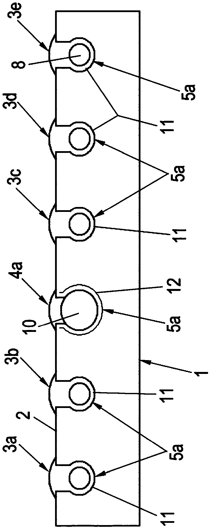
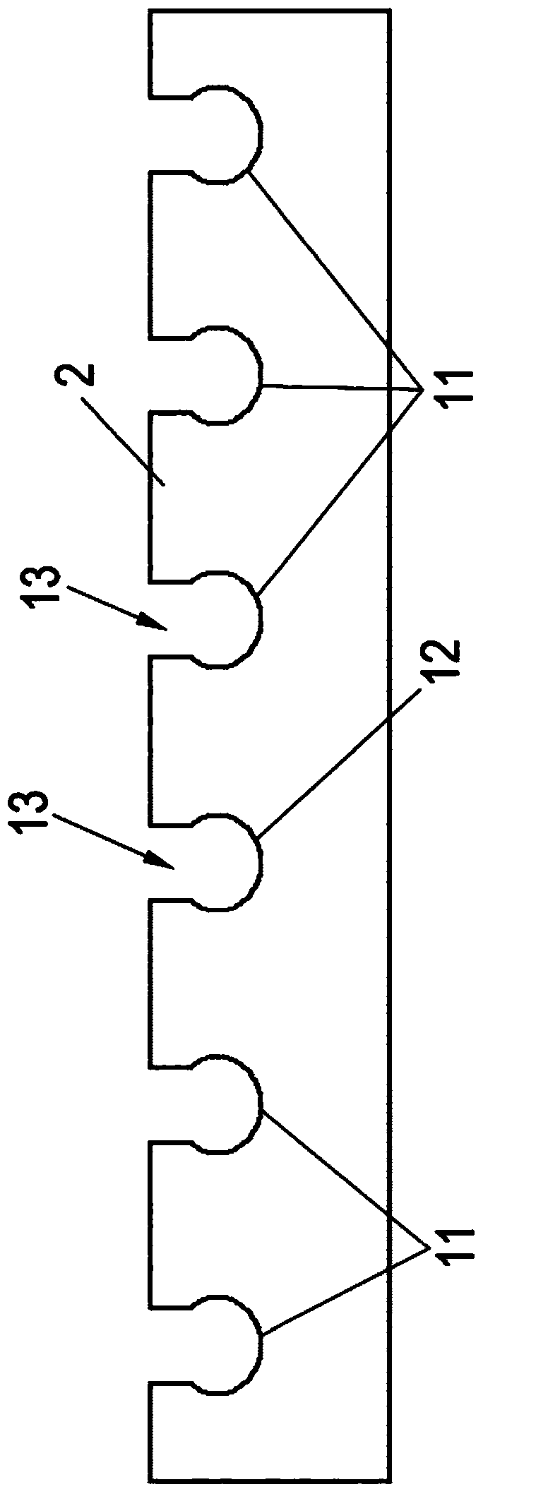
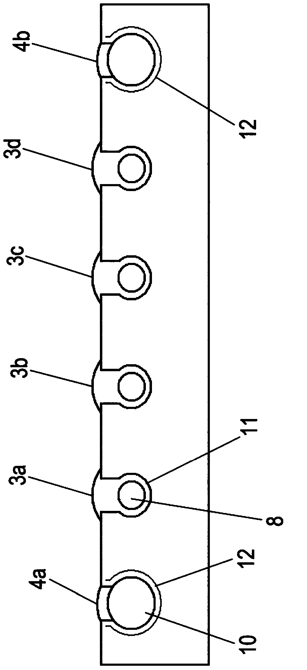
[0041] Roller bearing unit 1 ( Image 6 or in an alternate implementation: Figure 1 to Figure 5 ) has at least one roller cage 2 and a plurality of rolling elements 3, 3a, 3b, 3c, 3d, ... and 4, 4a, ...


PUM


Abstract

The invention relates to a pull-out guide device for furniture parts that are movable relative to one another comprising a roller bearing device, having the following: rolling elements (3a, b, c, d,... 4a, b), which are rotatably mounted in at least one rolling bearing cage (2), wherein at least one of the rolling elements (4a, b) is held and rotatably mounted in at least one bearing area of the bearing cage (2) by means of an interference fit, and wherein the bearing area(s) are plastically deformed in the region of the interference fit following the first insertion.

Description

technical field [0001] The invention relates to a pull-out guide for a drawer comprising a roller bearing arrangement with a plurality of rolling elements mounted in at least one roller bearing cage such that they Rotation is possible in various cases in at least one or more bearing regions assigned to the respective rolling element. Background technique [0002] Guide arrangements comprising roller bearing arrangements have been known for some time from the prior art, thus from DE 35 36 654 C2 and WO 2007 / 065180 A1. [0003] According to DE 35 36 654 C2, the bearing region has a bearing receptacle in which the shaft bearing pins of the rolling elements engage. For insertion into the bearing receptacle, the insertion gap is simply widened, and after the insertion of the bearing pin elastically shrinks again. The bearing pin is then held freely rotatable in the circular bearing receptacle with a loose fit. [0004] Furthermore, it is known from WO 2009 / 027342 A1 that the r...

Claims


Application Information

Patent Timeline
Patent Type & Authority Applications(China)
IPC IPC(8): A47B88/10A47B88/14A47B88/493
CPCA47B88/14A47B2210/0059A47B2210/004A47B88/10A47B88/493A47B88/487
Inventor 莱因哈德·布舍尔
Owner PAUL HETTICH
Why Eureka
Try Eureka