
Liquid tank and fuel cell

Active Publication Date: 2012-05-10
MURATA MFG CO LTD
View PDF56 Cites 7 Cited by
  • Summary
  • Abstract
  • Description
  • Claims
  • Application Information

AI Technical Summary

Benefits of technology

[0009]The present invention has been made in consideration of the above described issues, and an object thereof is to provide a liquid tank capable of reducing an influence of disturbance on measurement results and measuring accurate volume, and a fuel cell using the same.
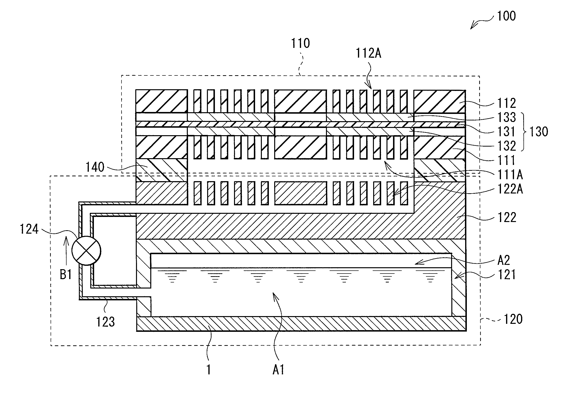
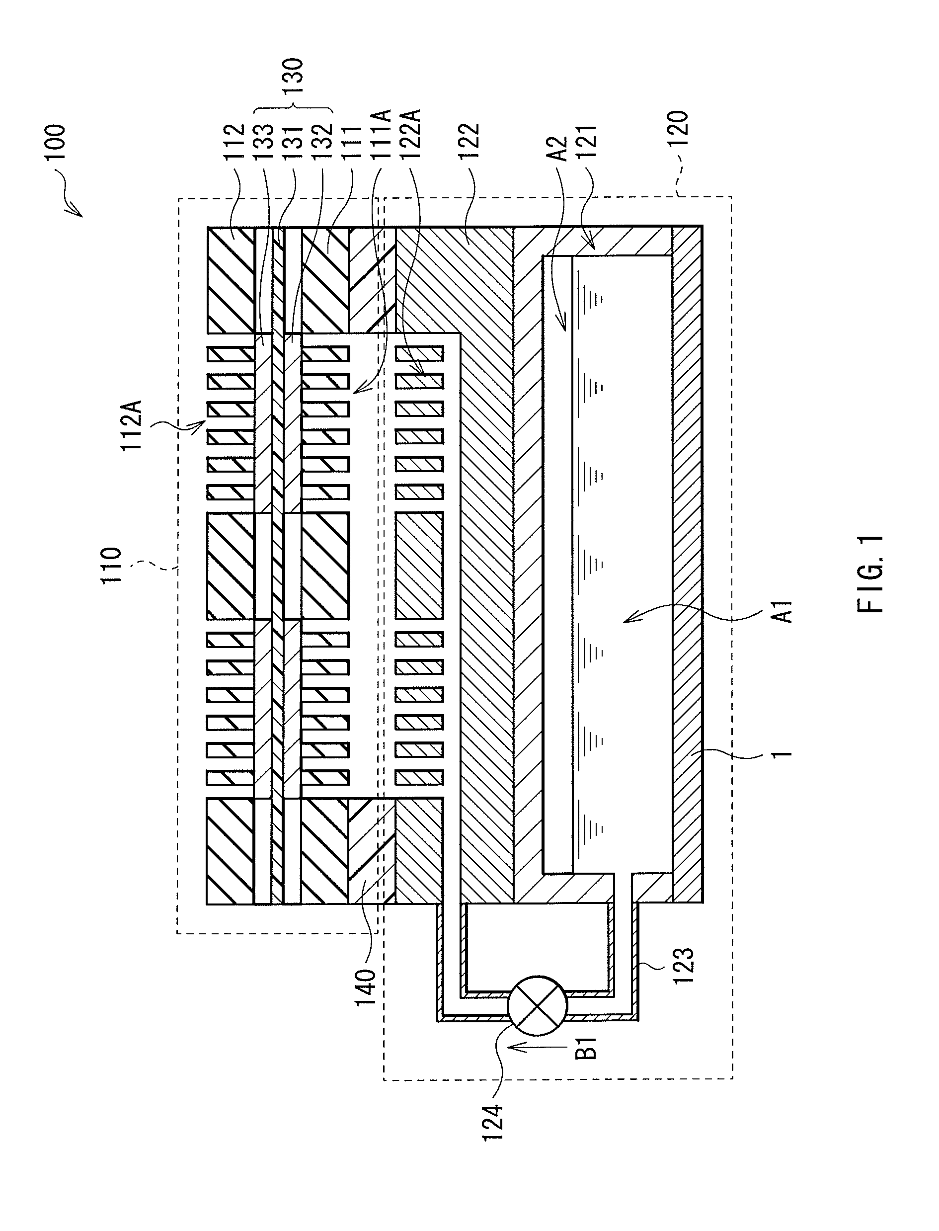
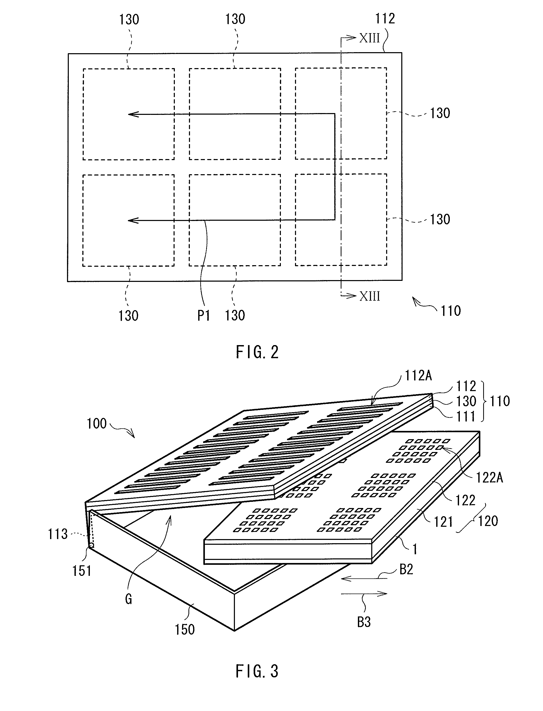
[0012]In the liquid tank according to the embodiment of the present invention, the pair of detection electrodes, provided on the front face of the first board of the detector, directly or indirectly contact with the liquid inside the liquid container section, whereby the stray capacitance generated between the detection electrodes is detected. The second board having the shielding electrode is arranged on the back face side of the first board, whereby, even when a hand or the like is brought close to the detector, the detection electrodes are prevented from sensing a stray capacitance generated as a result.
[0014]The liquid tank according to the embodiment of the present invention is provided with the pair of detection electrodes on the front face of the first board of the detector, and allows the pair of detection electrodes to contact directly or indirectly with the liquid inside the liquid container section to detect the stray capacitance, while the second board having the shielding electrode is arranged on the back face side of the first board. This makes it possible to reduce an influence of disturbance on measurement results, and to measure the accurate volume. Therefore, configuring the fuel cell by using this liquid tank makes it possible to estimate an available remaining time based on the accurate volume of the liquid fuel. In particular, it is suitable for fuel cells to be mounted to electronic devices intended for portable use, making it possible to improve the convenience of devices.

Problems solved by technology

For this reason, a water level changes due to surface tension, whereby this method has an issue in that it is not possible to measure accurate volume.
Additionally, the method of Patent Document 2 has an issue in that, since detection sensitivities are provided for both sides of the printed board, a detection result changes when a hand or the like is brought close thereto.

Method used


Image

  • Liquid tank and fuel cell
  • Liquid tank and fuel cell
  • Liquid tank and fuel cell

Examples


examples

[0068]Further, specific Examples of the present invention are described. [No. 1 to No. 8]

[0069]The detectors 1 having a size of 19 mm by 35 mm were fabricated in a manner similar to that in the above described embodiment. In fabrication, four-layer printed boards were used as the first board 10 to the fourth board, and the pair of detection electrodes 12A and 12B having the shape of the comb-tooth as shown in FIG. 5 were formed on the first board 10 in such a manner as to engage with each other with a spacing therebetween. On the second board 20, the shielding electrode 22, which is either solid as shown in FIG. 6 or mesh-shaped as shown in FIG. 8, was formed. Only a via hole was formed in the third board 30. On the fourth board 40, the three lands 42A to 42C were formed as shown in FIG. 10. Among the three lands 42A to 42C, the two lands 42A and 42B were connected with the detection electrodes 12A and 12B, respectively, and the remaining one land 42C was connected to the shielding ...


PUM


Abstract

Provided are a liquid tank capable of reducing an influence of disturbance on measurement results and measuring accurate volume, and a fuel cell using the same. One face of a liquid container section is structured by a detector in which a first board to a fourth board each configured of a printed board are stacked in order. A pair of detection electrodes 12A and 12B are provided on a front face of the first board, and this pair of detection electrodes 12A and 12B are allowed to contact directly or indirectly to a liquid fuel inside the liquid container section to detect a stray capacitance. A back face side of the first board is disposed with the second board having a shielding electrode 22. Even when a hand or the like is brought close to the detector, the detection electrodes 12A and 12B are prevented from sensing the stray capacitance generated as a result.

Description

TECHNICAL FIELD[0001]The present invention relates to a liquid tank to contain liquid fuel or the like for a fuel cell, and a fuel cell provided therewith.BACKGROUND ART[0002]Usually, a fuel cell system, which uses liquid fuel such as methanol or a hydrogen generation auxiliary agent such as water, is internally equipped with a tank to store liquid. In the fuel cell system, in order to estimate a remaining time available for a device connected thereto, it is imperative that a remaining amount of liquid in the tank be accurately detected.[0003]One method available for estimating the remaining liquid amount in the tank, as far as an active fuel cell in which fuel is actively sent in liquid form by use of a pump or the like is concerned, is to count the total number of times the pump has been driven. The fuel in the tank is found by a formula V1−V2×n, where V1 is the inner volume of the tank, V2 is a volume sent in liquid form per one time the pump is driven, and n is the total number ...

Claims


Application Information

Patent Timeline
IPC IPC(8): G01F23/26
CPCG01F23/268H01M8/04216G01F23/263H01M8/0438Y02E60/50H01M8/04313
Inventor SHIMURA, JUSUKE
Owner MURATA MFG CO LTD
Learn More