
Pneumatic tire

a technology of pneumatic tires and braking systems, applied in the field of pneumatic tires, can solve the problems of reduced on-snow performance, reduced on-snow braking performance, so as to achieve improved on-snow performance and on-snow performance, and good balance

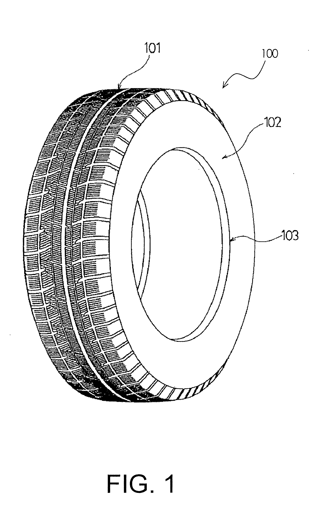
Inactive Publication Date: 2012-05-17
THE YOKOHAMA RUBBER CO LTD
View PDF3 Cites 7 Cited by
  • Summary
  • Abstract
  • Description
  • Claims
  • Application Information

AI Technical Summary

Benefits of technology

[0007]An object of the present invention is to provide a pneumatic tire improved in on-ice performance and on-snow performance in good balance.

Problems solved by technology

However, merely reducing the ratio of groove area in the tread portion causes reduction in on-snow performance.
In other words, there is a trade-off relationship between the on-ice performance and the on-snow performance, and it is extremely difficult to achieve both performances in good balance.
Moreover, an on-ice braking performance tends to be reduced due to reduction in a contact area.

Method used


Image

  • Pneumatic tire
  • Pneumatic tire
  • Pneumatic tire

Examples


examples

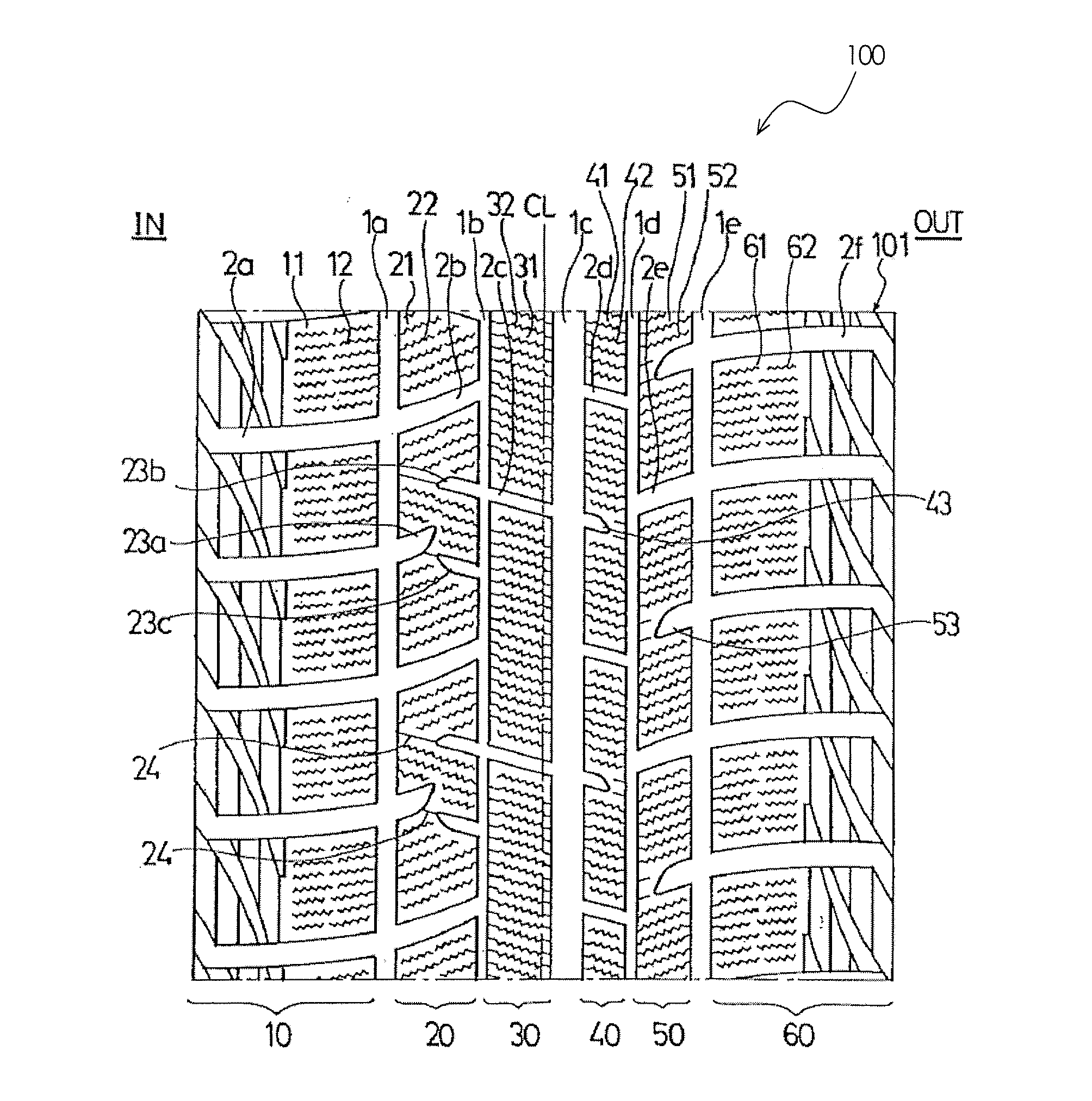
[0077]Pneumatic tires of Examples 1, 2 with the following configuration were prepared. Each pneumatic tire had a tire size of 215 / 60R16 and such an asymmetrical tire pattern that the tire was to be mounted on a vehicle with a designated side thereof facing an outside of the vehicle. A tread portion of each pneumatic tire was provided with multiple longitudinal grooves extending in a tire circumferential direction and multiple lateral grooves extending in a tire width direction, and the longitudinal grooves and the lateral grooves defined multiple block rows including multiple blocks. In each of the multiple blocks included in a block row located between a block row in a tire shoulder on the inner side of the vehicle and a block row on a tire equator, three closed grooves including one first closed groove and two second closed grooves were provided. Here, one end of the first closed groove was opened to a longitudinal groove which was adjacent to the block and located on the shoulder...


PUM


Abstract

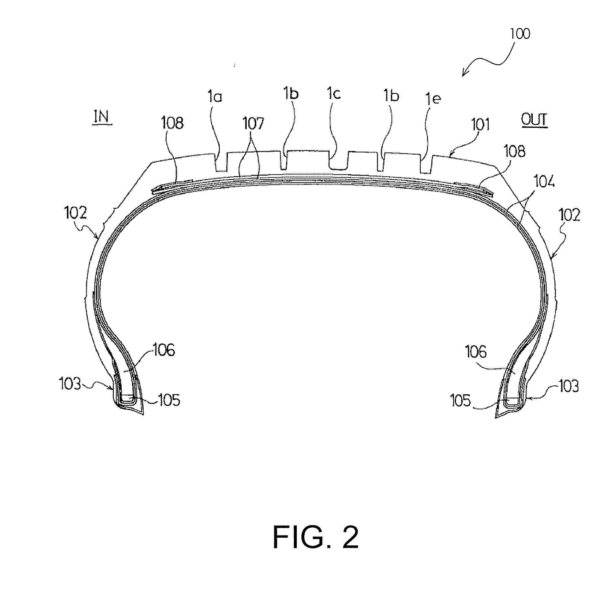
A pneumatic tire improved in on-ice performance and on-snow performance in good balance. The pneumatic tire includes a tread portion extending in a tire circumferential direction and forming a ring shape, a pair of sidewall portions on both sides of the tread portion, respectively, and a pair of bead portions on inner sides of the sidewall portions in a tire radial direction, respectively. The tread portion includes a plurality of longitudinal grooves extending in the tire circumferential direction and a plurality of lateral grooves extending in a tire width direction. The longitudinal and lateral grooves define a plurality of block rows each including a plurality of blocks. Each of the plurality of blocks included in at least one of the block rows includes at least three closed grooves including at least one first closed groove and at least one second closed groove.

Description

CROSS-REFERENCE TO RELATED APPLICATIONS[0001]This application claims priority to Japanese Patent Application No. JP2010-255069, filed on Nov. 15, 2010, Japanese Design Application No. JP2010-027743, filed on Nov. 18, 2010 and Japanese Patent Application No. JP2011-088033, filed on Apr. 12, 2011. The entire disclosures of Japanese Patent Application No. P2010-255069, Japanese Design Application No. JP2010-027743 and Japanese Patent Application No. JP2011-088033 are hereby incorporated herein by reference.BACKGROUND[0002]1. Field of the Invention[0003]The present invention relates to a pneumatic tire suitable for winter use, and more specifically relates to a pneumatic tire that has improved on-ice performance and on-snow performance and good balance.[0004]2. Background Information[0005]A pneumatic tire for winter use such as a studless tire conventionally has the following configuration. Multiple longitudinal grooves extending in a tire circumferential direction and multiple lateral ...

Claims


Application Information

Patent Timeline
Patent Type & Authority Applications(United States)
IPC IPC(8): B60C11/11B60C11/03
CPCB60C11/0306B60C11/0304B60C2011/1213B60C2011/0372B60C11/12B60C2011/0381B60C11/1236
Inventor NAGAYASU, MASAAKIHASHIMOTO, YOSHIMASAFURUSAWA, HIROSHIENDOU, KENICHIROUSATO, KENICHI
Owner THE YOKOHAMA RUBBER CO LTD
Learn More