
Pneumatic tire

a technology of pneumatic tires and tyres, applied in the direction of tyre tread bands/patterns, vehicle components, transportation and packaging, etc., can solve the problems of deteriorating steering stability, improve cornering performance on snowy roads, and suppress the reduction in rigidity of the outboard middle land portion

Active Publication Date: 2019-04-30
SUMITOMO RUBBER IND LTD
View PDF14 Cites 2 Cited by
  • Summary
  • Abstract
  • Description
  • Claims
  • Application Information

AI Technical Summary

Benefits of technology

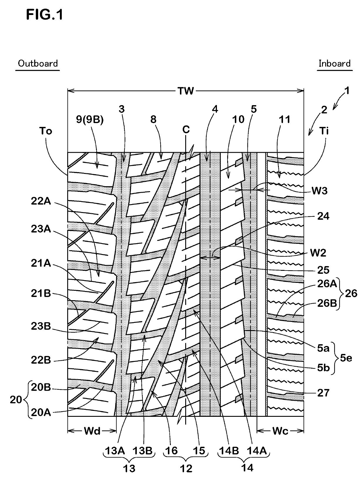
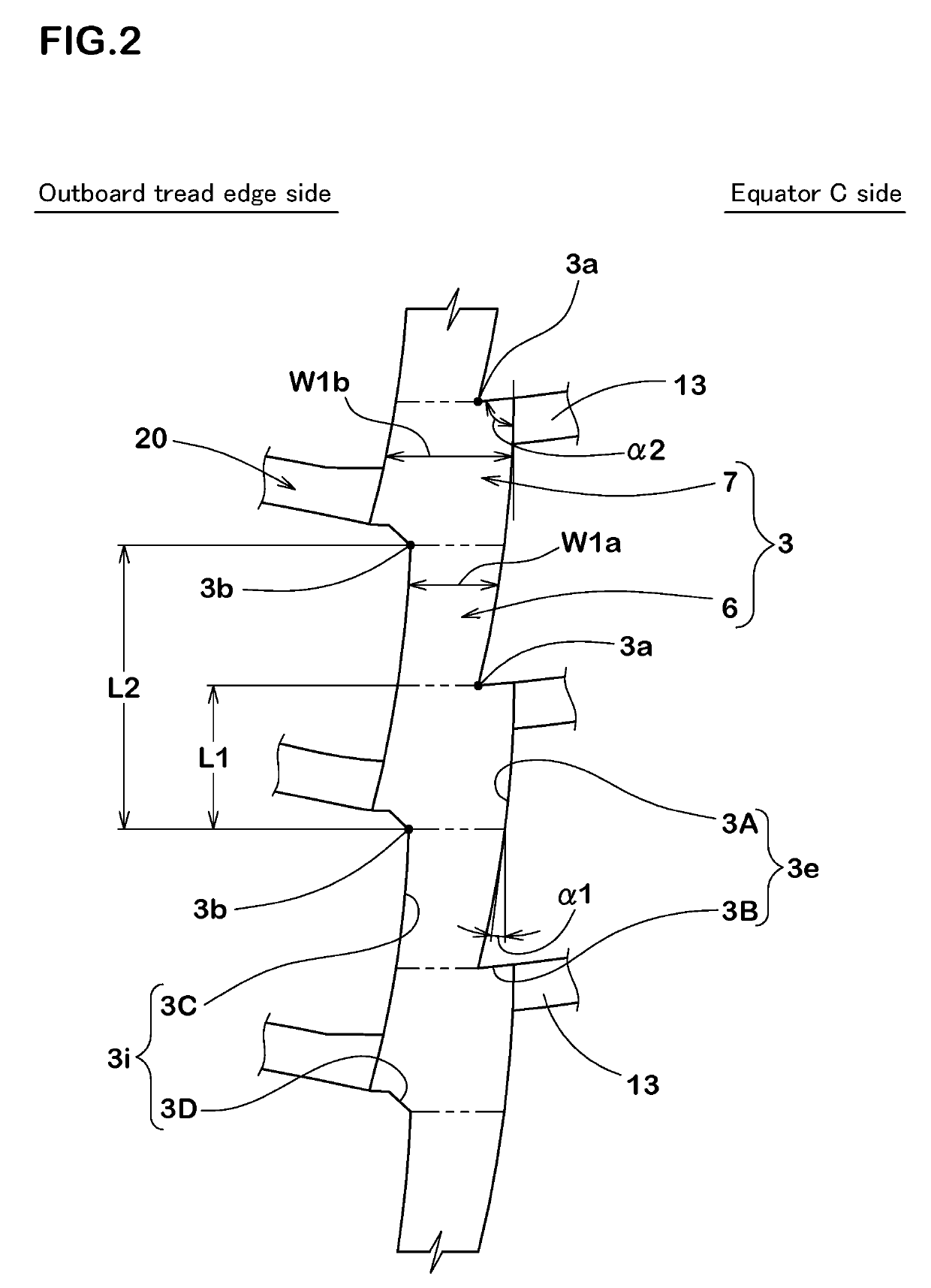
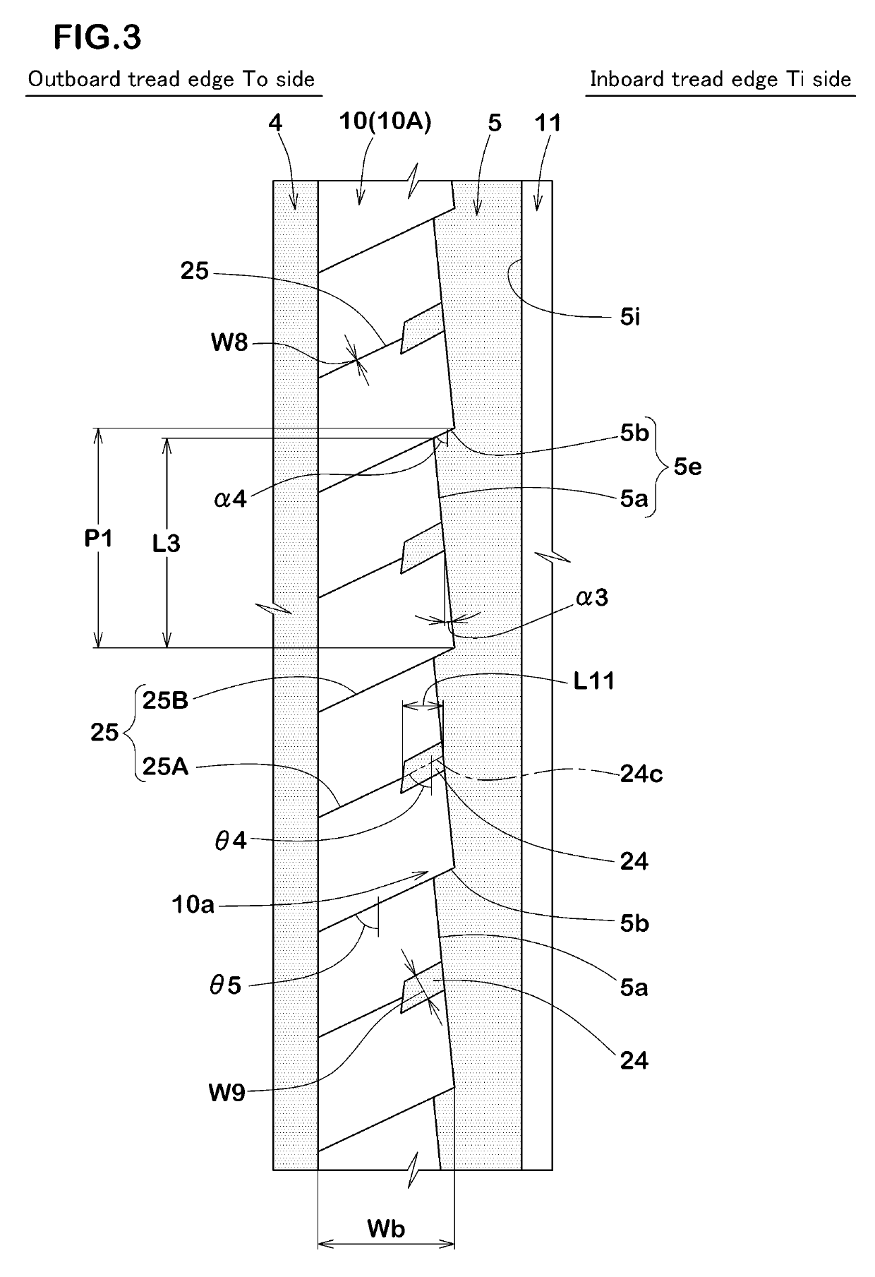
The present invention is related to a pneumatic tire design for snowy roads. The tire has a special middle land portion with middle inclined grooves, outboard middle lug grooves, and inboard middle lug grooves. The first main groove has wider portions and is positioned at the outboard tread edge. The second main groove has protruded portions that compress snow and generate a snow-shearing force to improve performance on snowy roads. The middle inclined grooves are not directly connected to the first or second main grooves to maintain the steering stability of the tire. The outboard middle lug grooves connect the second portions of the first main groove to the middle inclined grooves, and the inboard middle lug grooves connect the middle inclined grooves and the second main groove. This design improves the on-snow performance and maintains the steering stability of the tire.

Problems solved by technology

Unfortunately, in the above mentioned pneumatic tire, there is a problem that the steering stability deteriorates based on reduction of tread rigidity.

Method used


Image

  • Pneumatic tire
  • Pneumatic tire
  • Pneumatic tire

Examples


example

Example A

[0144]Pneumatic tires of 215 / 60R16 having a basic tread pattern illustrated in FIG. 1 or patterns illustrated in FIGS. 6 to 9 were manufactured based on details shown in Table 1, and then on-snow performance and steering stability of these tires was tested. The common specifications of tires are as follows. Note that FIG. 6 illustrates a tread pattern of Ex. 6 where the second inclined elements and groove edges of the outboard middle lug grooves are not smoothly connected. FIG. 7 illustrates a tread pattern of Ex. 7 where the first inclined elements are smooth arc shapes that convex toward the outboard. FIG. 8 illustrates a tread pattern of Ex. 8 where the inner ends of the first middle inclined elements are not provided on the tire equator. FIG. 9 illustrates a tread pattern of Ref. 1 where the outboard middle lug grooves and the inboard middle lug grooves are overlapped with each other in the circumferential direction of the tire.

[0145]Tread width TW: 166 mm

[0146]Groove d...

example b

[0159]Pneumatic tires of 215 / 60R16 having a basic tread pattern illustrated in FIG. 1 were manufactured based on details shown in Table 2, and then on-snow performance and steering stability of these tires was tested. The common specifications of tires are as follows.

[0160]Tread width TW: 166 mm

[0161]Average groove width W4 of first middle inclined element: 7 mm

[0162]Maximum groove width W4b of first middle inclined element: 11 mm

[0163]Minimum groove width W4a of first middle inclined element: 3 mm

[0164]The test procedures are as follows:

[0165]On-Snow Performance:

[0166]Each test tire was mounted on a passenger car with a displacement of 2,400 cc as all the wheels under the following conditions. Then, a test driver drove the vehicle on a compacted snow road of a test course, and evaluated the traveling characteristic relating to steering stability such as handle stability, rigidity feeling, traction and grip by his feeling. The results are indicated in scores based on Ref. 1 being 10...

example c

[0173]Pneumatic tires of 215 / 60R16 having a basic tread pattern illustrated in FIG. 1 were manufactured based on details shown in Table 3, and were tested. The common specifications of tires are as follows. The common specifications of tires are as follows. Note that total groove areas of the tread portions illustrated in FIGS. 1, 13 and 14 are the same. Furthermore, the Ref. 1 has the read pattern illustrated in FIG. 1 where the middle inclined grooves extend smoothly toward the inboard and communicate with the first main groove, and no inboard middle lug grooves are provided.

[0174]Tread width TW: 166 mm

[0175]Groove depths of first middle inclined elements: 8.2 mm

[0176]Groove depths of second middle inclined elements: 5.4 mm

[0177]Groove depths of outboard middle lug grooves: 5.8 mm

[0178]Groove depths of inboard middle lug grooves: 4.0 mm

[0179]groove depths of middle lateral lug grooves: 6.3 mm

[0180]groove depths of inboard middle sipes: 4.0 mm

[0181]On-Snow Performance:

[0182]Each te...


PUM


Abstract

Performance on snowy roads is improved. Provided is a pneumatic tire, of which the mounting orientation on a vehicle is indicated. An outer middle land part is formed between a first major groove and a second major groove. The first major groove has first portions and second portions alternately formed in the tire circumferential direction, the second portions being wider than the first portions. The outer middle land part is provided with a plurality of middle inclined grooves not directly interconnected with either the first major groove or the second major groove, a plurality of outer middle lug grooves connecting the second portions of the first major groove and the middle inclined grooves, and inner middle lug grooves connecting the middle inclined grooves and the second major groove. The outer middle lug grooves are provided to different positions in the tire circumferential direction than the inner middle lug grooves.

Description

TECHNICAL FIELD[0001]The present invention relates to a pneumatic tire with an improved on-snow performance while maintaining steering stability.BACKGROUND ART[0002]Pneumatic tires for winter have a chance to be traveling on a dry road in addition to a snowy road. Accordingly, such a pneumatic tire for winter has been requested to improve steering stability as well as on-snow performance in good balance at a high level.[0003]For example, in order to improve the on-snow performance by increasing snow-shearing force, a pneumatic tire including a tread portion provided with a lateral groove having a large volume has been proposed.[0004]Unfortunately, in the above mentioned pneumatic tire, there is a problem that the steering stability deteriorates based on reduction of tread rigidity.CITATION LISTPatent LiteraturePatent document 1: Japanese Unexamined Patent Application Publication No. 2011-51425Patent document 2: Japanese Unexamined Patent Application Publication No. 2000-509675SUMMAR...

Claims


Application Information

Patent Timeline
Patent Type & Authority Patents(United States)
IPC IPC(8): B60C11/03B60C11/12
CPCB60C11/0332B60C11/0304B60C11/0306B60C11/1236B60C11/0302B60C2011/0395B60C2011/0334B60C2011/0341B60C2011/0346B60C2011/0353B60C2011/0358B60C2011/0374B60C2011/0376B60C2011/0381B60C2011/0386
Inventor TAKAGI, KEIJIKANEMATSU, YOSHIAKIYAMAOKA, HIROSHI
Owner SUMITOMO RUBBER IND LTD
Learn More