
Tire mold, tire, and tire manufacturing method

a tire mold and tire technology, applied in the direction of non-skid devices, transportation and packaging, other domestic objects, etc., can solve the problems of reducing the rigidity of the entire block, reducing the on-ice performance and on-snow performance, and reducing the contact area of the tire ground, so as to and improve the on-ice performance and on-snow performance. , the effect of excellent on-ice performan

Active Publication Date: 2014-07-10
BRIDGESTONE CORP
View PDF9 Cites 2 Cited by
  • Summary
  • Abstract
  • Description
  • Claims
  • Application Information

AI Technical Summary

Benefits of technology

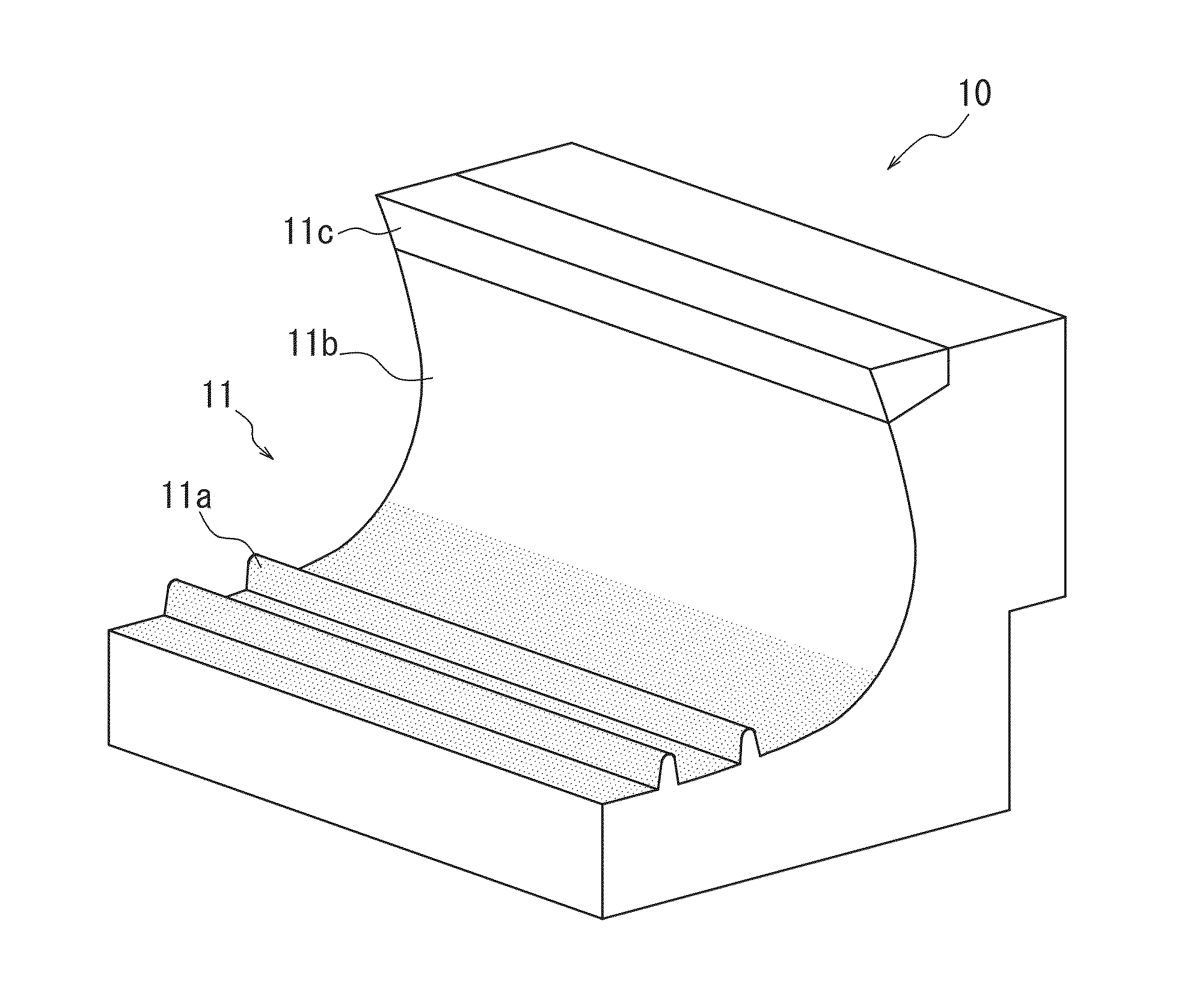
The present invention provides a tire with improved on-ice performance and on-snow performance, a tire mold for molding the tire, and a method for manufacturing the tire. By using a technique for providing sipes in a block, the number of sipes can be controlled to maintain block rigidity and prevent collapse, resulting in improved tire ground contact area and better on-ice and on-snow performance. The desired tread surface properties can be obtained by using the mold, resulting in a tire with excellent on-ice and on-snow performance.

Problems solved by technology

This leads to the problem of reduced tire ground contact area, which ends up lowering the on-ice performance and on-snow performance.
On the other hand, with the technique disclosed in PTL 2 to use foam rubber in the cap rubber, the rigidity of the entire block may decrease due to the use of foam rubber, and therefore the wear resistance of the tire is not necessarily sufficient.
Furthermore, with the technique disclosed in PTL 3 to provide protrusions with a pointed edge on the surface of the tread portion, the rigidity of the protrusions is low, and therefore particularly when a large load is applied on the tires, such as during an increased load on the front wheels due to the vehicle nose-diving, the protrusions may be crushed, preventing the desired performance from being obtained.
As a result, the desired on-ice performance and on-snow performance may not be obtained.
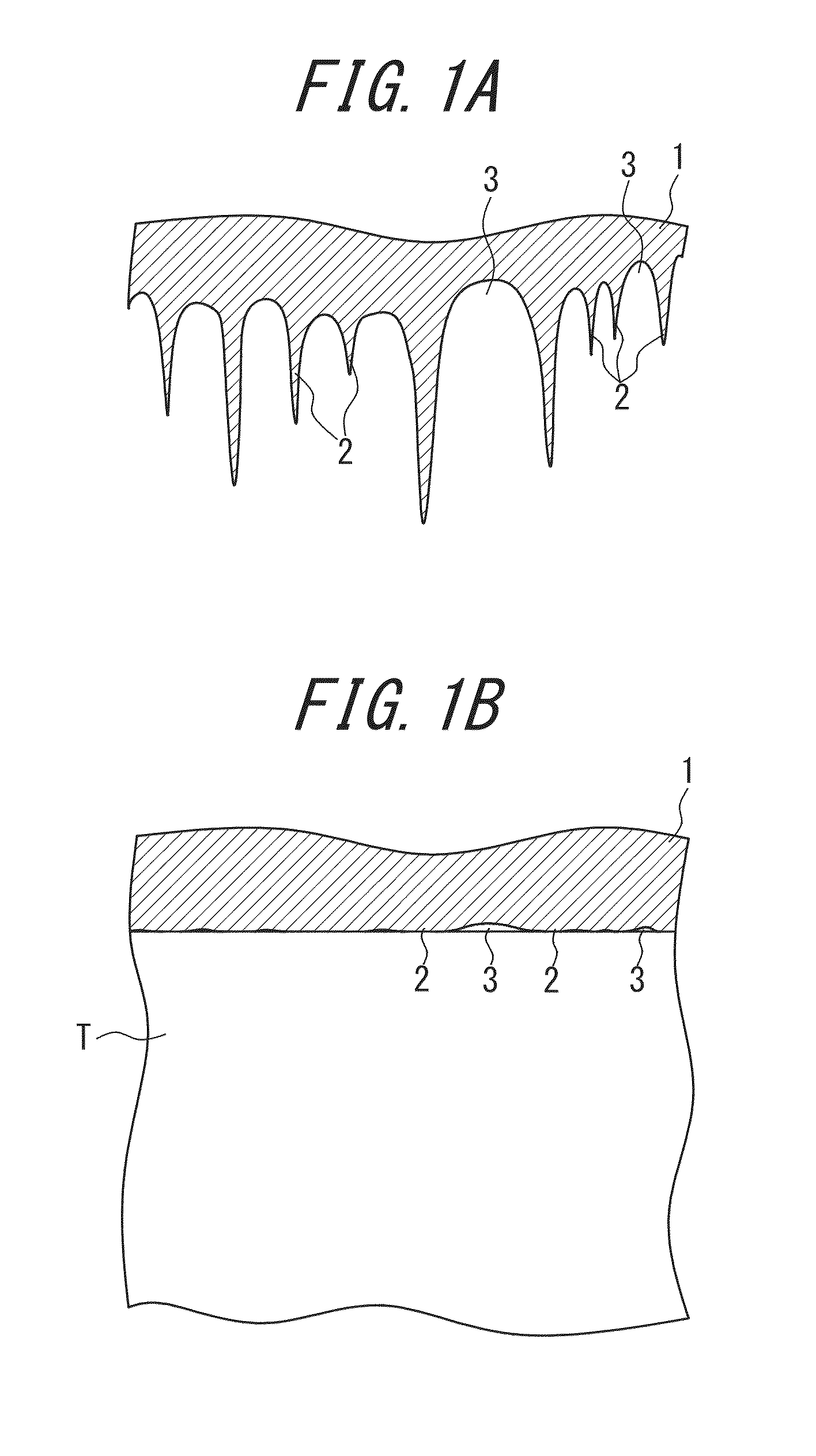
The inventors repeatedly examined tires using the techniques disclosed in PTL 1 to 3 and further discovered that, while the reason is unclear, such conventional tires have the problem that on-ice performance and on-snow performance are not sufficiently obtained particularly for newly produced tires.

Method used


Image

  • Tire mold, tire, and tire manufacturing method
  • Tire mold, tire, and tire manufacturing method
  • Tire mold, tire, and tire manufacturing method

Examples


examples

[0067]In order to confirm the effects of the present invention, a tire according to an Inventive Example and a tire according to a Comparative Example were produced as described below, and tires according to Conventional Examples were also prepared.

[0068]The tires were molded using an aluminum tire mold in which the tread molding surface of the mold was formed by a projection material projecting step using the projection material with the specifications listed in Table 1.

[0069]Note that in Table 1, the “projection time” refers to the projection time of the projection material per mold. For each mold, the operator projected projection material onto the tread molding surface for the above projection time while shifting the position. Furthermore, each tire was molded using 9 molds in which the tread molding surface was formed in this way.

TABLE 1Inventive ExampleComparative ExampleConventional Example 1Conventional Example 2Projectionmaterialzirconzirconalundumglass beadMaterialspherici...


PUM

PropertyMeasurementUnit
particle diameteraaaaaaaaaa
average particle diameteraaaaaaaaaa

Abstract

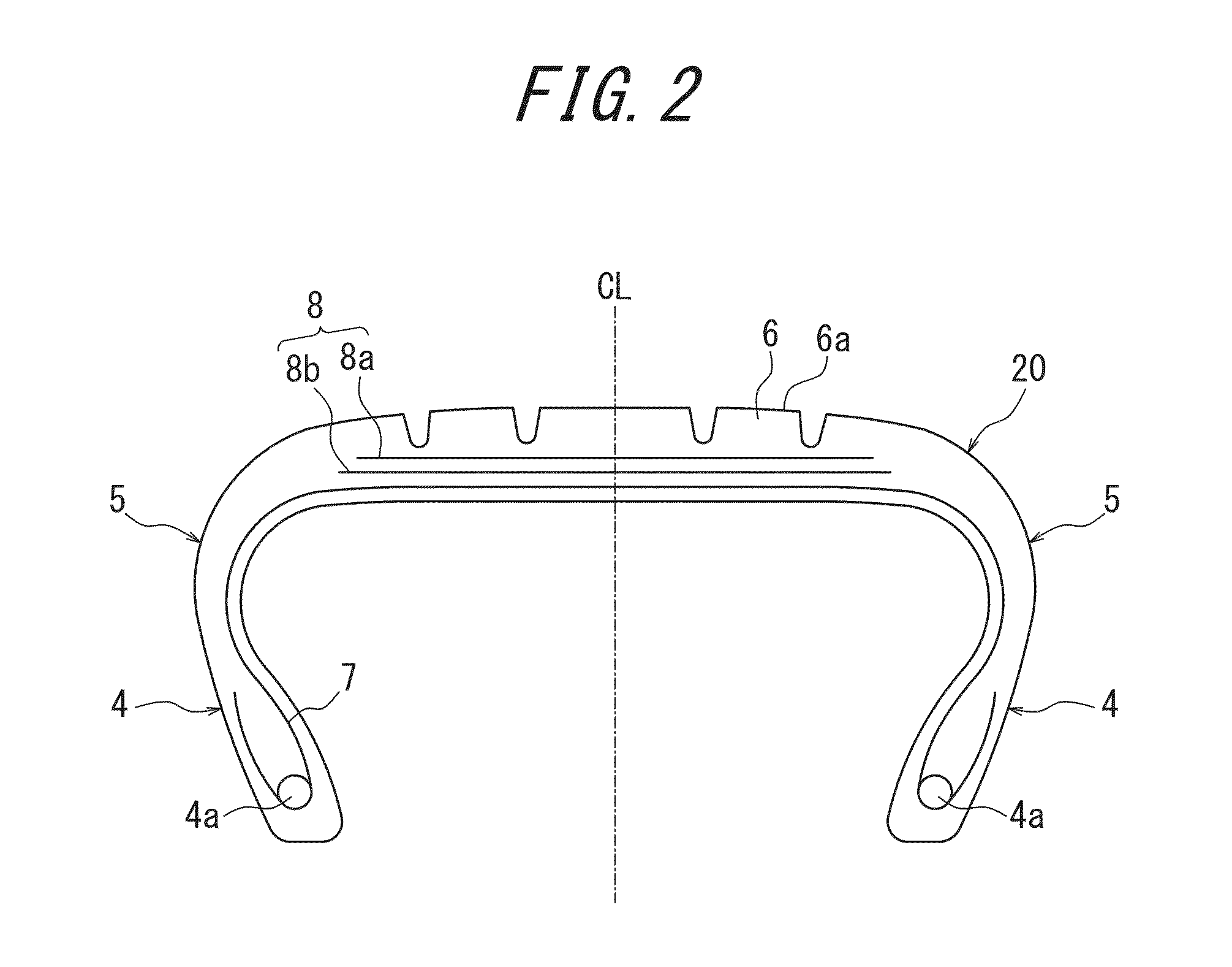
The tread surface of a tire according to the present invention is molded with a tire mold having a tread molding surface, and at least a portion of the tread molding surface is formed by projecting spherical projection material having a predetermined sphericity and causing the spherical projection material to collide.

Description

TECHNICAL FIELD[0001]The present invention relates to a tire mold, tire, and tire manufacturing method.BACKGROUND ART[0002]In the past, a variety of approaches have been taken with winter tires in order to improve on-ice performance and on-snow performance.[0003]For example, JP2002-192914A (PTL 1) proposes a technique for providing a plurality of sipes on each block formed in the tread portion in order to increase the edge component in the tire ground contact area while also improving snow-biting and improving driving performance of the tire on icy and snowy roads (frozen roads and roads with accumulated snow).[0004]On the other hand, JP11-301217A (PTL 2), for example, proposes a technique for a tire having tread rubber with a so-called cap and base structure formed by cap rubber and base rubber. By using foam rubber as the cap rubber, this technique greatly improves water drainage and improves on-ice performance and on-snow performance.[0005]Furthermore, JP2009-067378A (PTL 3), for...

Claims


Application Information

Patent Timeline
Patent Type & Authority Applications(United States)
IPC IPC(8): B29D30/06B60C11/13
CPCB60C11/13B29D30/0662B29D30/0606B29C33/424B29D2030/0612B29D2030/0616B29L2030/00B60C11/00
Inventor KATSUNO, HIROYUKIWATABE, RYOICHIKATAYAMA, MASAHIRO
Owner BRIDGESTONE CORP
Learn More