Over air-barrier electrical box

Inactive Publication Date: 2012-05-17
FUNK ROBERT ANTHONY +1
View PDF6 Cites 0 Cited by
  • Summary
  • Abstract
  • Description
  • Claims
  • Application Information

AI Technical Summary

Problems solved by technology

Electrical devices mounted on the exteriors of buildings present certain challenges and problems, most of which are associated with water.
Even when such breaches are done carefully and are properly sealed, over years or decades of exposure to air and water, the sealing seal deteriorates and rainwater gains access to the interior of the wall, resulting in rotting, electrical malfunction, and other problems, most of which are expensive to repair and some of which can be dangerous.

Method used


Image

  • Over air-barrier electrical box
  • Over air-barrier electrical box
  • Over air-barrier electrical box

Examples


Embodiment Construction

Structure

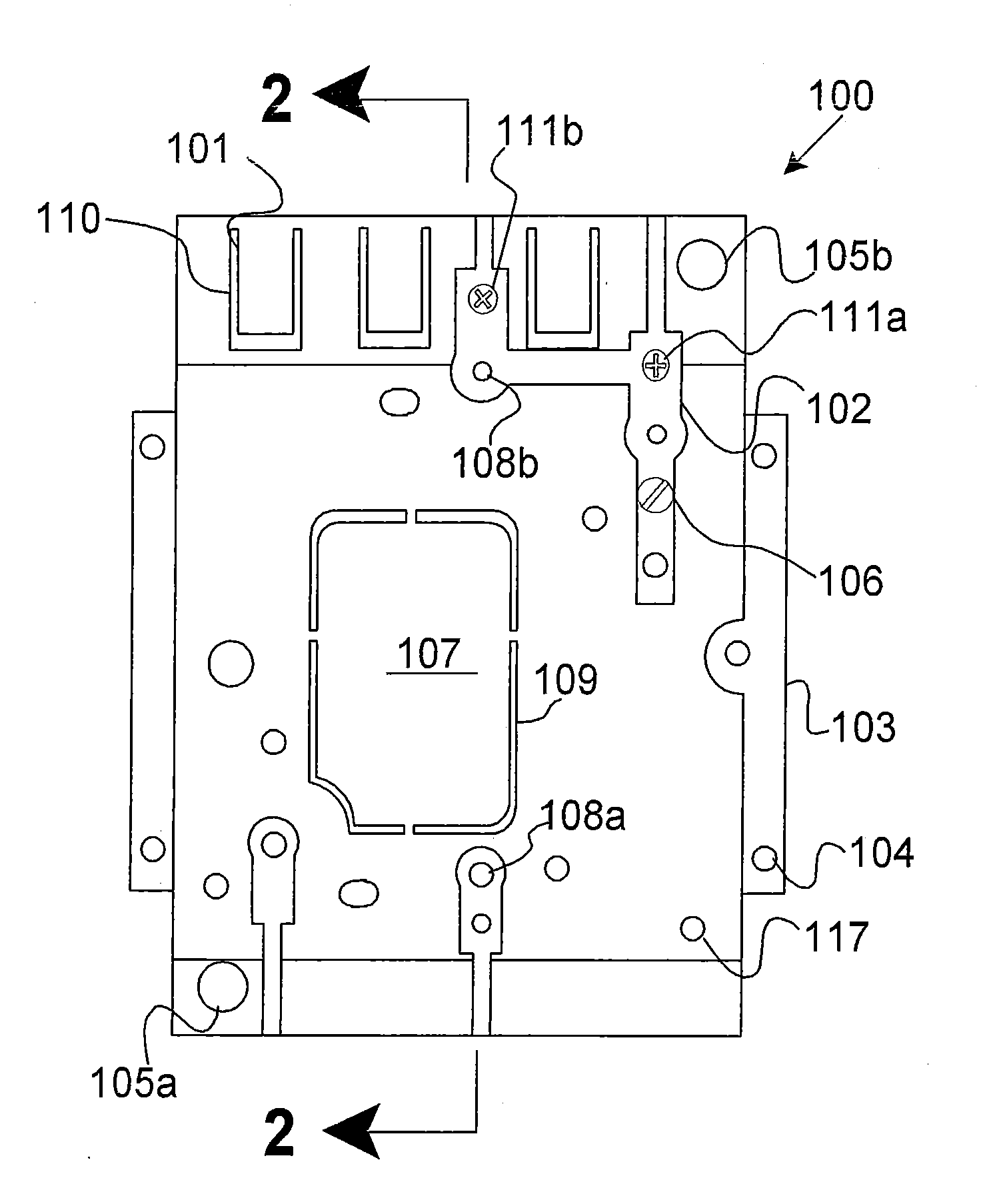
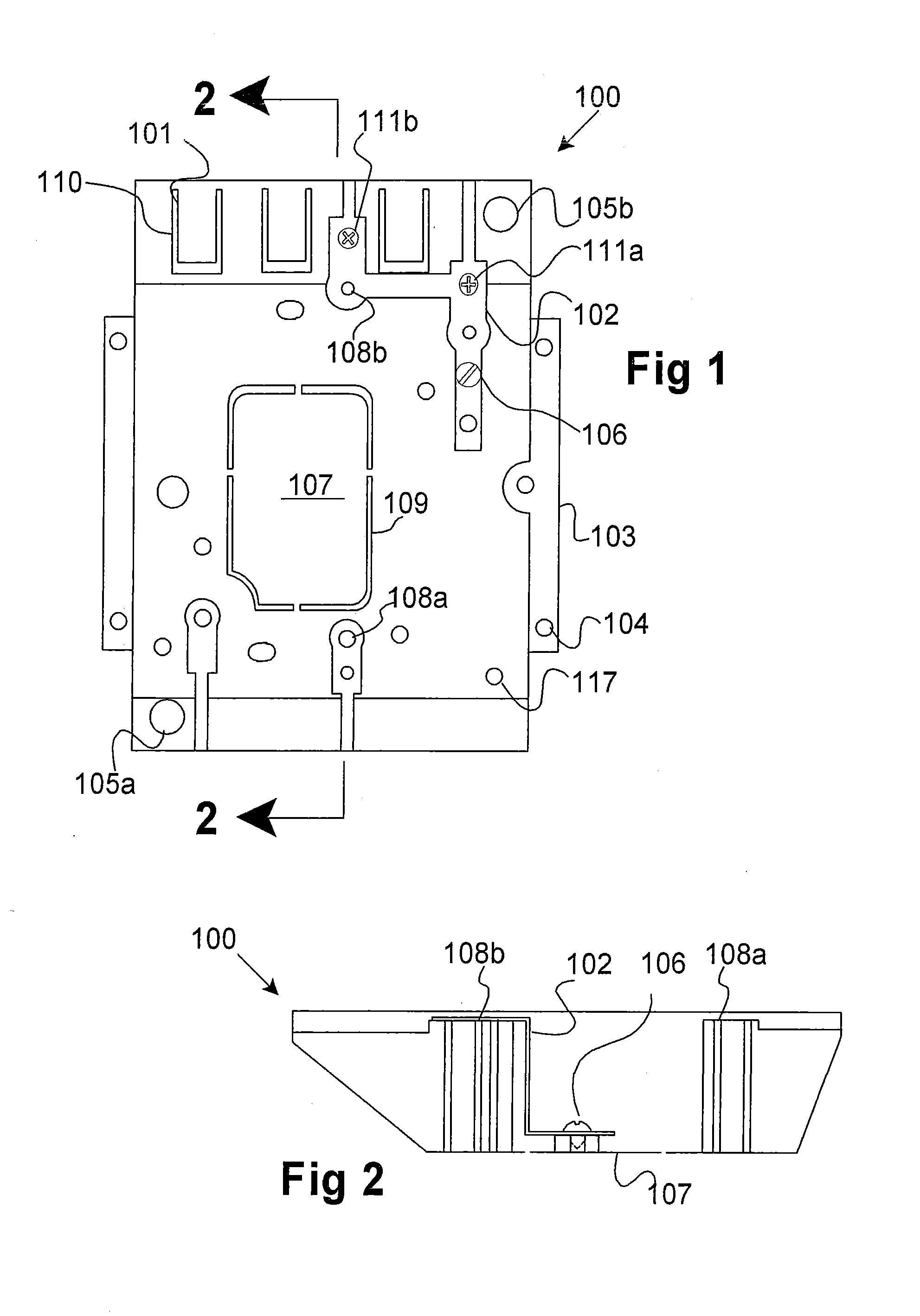
[0022]Referring first to FIGS. 1 and 2 an electrical box 100 according to the invention is illustrated without a cover or face plate. The electrical box 100 is constructed from any suitable material. Although a variety of materials may be employed without adversely affecting the function, novelty, or objectives of the invention, a preferred material is a plastic material, and more specifically, virgin polypropylene. The box 100 may be manufactured to meet the specifications of a particular application, but generally a rectangular box is preferred, being approximately 9.5 cm in its shortest dimension, referred to herein as its width; approximately 13.8 cm in its longest dimension, referred to herein as its length; and have a depth of approximately 2.5 cm.

[0023]The electrical box 100 is provided with a plurality of attachment holes, one of which is designated 104, for attaching the box 100 to the exterior surface of the building, as will be described below. These attachment h...


PUM


Abstract

The invention disclosed and claimed here includes an electrical box and a system for mounting the electrical box to the exterior of a structure. When used with a mating rain shield, the invention provides a water-proof means for mounting electric devices on the exterior of structures. The electrical box can be used as a primary electrical box or it can be used as an extension of a pre-existing electrical box. The invention includes a face-plate that is attached to the electrical box. The electrical box is universal in two respects. First, it can be mounted to and used as an extension for a wide variety of pre-existing electrical boxes, and second, by employing a variety of face-plates, the electric box can be adapted to receive many different types of electric devices, such as plugs, sockets, lamps, lights, and electric accessories.

Description

BACKGROUND[0001]The field of the invention is electric junction boxes, particularly those used in exterior applications in conjunction with rain shields and rain-shielded mounting boxes.[0002]The term “electrical box” or, alternatively, “box” is used herein as is standard in the art, which is to say a housing within which one or more electrical connections are made. While many electrical boxes are rectangular, neither the term “electrical box” nor the invention is restricted to rectangular structures. The terms “back”, “bottom” and “back / bottom” when used in reference to a surface or side of the electrical box mean the same thing. If the box is being held on one's hand and one is looking into the box, the term “bottom” is more descriptive. If the box is mounted vertically for use, the term “back” is more descriptive.[0003]The term “electrical device” includes any device that may be mounted on the exterior of a building and that is powered by, controls, or otherwise interacts with el...

Claims


Application Information

Patent Timeline
IPC IPC(8): H01H9/02
CPCH02G3/088
Inventor FUNK, ROBERT ANTHONYFUNK, ANTHONY ISAAC
Owner FUNK ROBERT ANTHONY
Why Eureka
Try Eureka