Modular Flight Vehicle With Wings

a technology of flight vehicle and module, applied in the field of flight vehicles, can solve the problems of failure and loss of helicopters, lack of vertical takeoff or landing (vtol) or even short takeoff or landing (stol) capabilities of most airplanes, and increase the cost of maintenance and repair, so as to improve the lift characteristics and improve reliability. the effect of the effect of the li

Inactive Publication Date: 2012-05-17
SHAW DONALD ORVAL
View PDF28 Cites 65 Cited by
  • Summary
  • Abstract
  • Description
  • Claims
  • Application Information

AI Technical Summary

Benefits of technology

[0041]Due to issues with currently available vertical lift vehicles, a need exists for a vertical lift vehicle that has improved lift characteristics, reduced cost, and increased reliability. The present invention addresses these needs.

Problems solved by technology

While airplanes have excellent lifting capacity and altitude capabilities, most airplanes lack vertical takeoff or landing (VTOL) or even short takeoff or landing (STOL) capabilities, and they typically require a large open space for takeoff and landing.
In many rugged landing sites, airplanes are not suitable.
Helicopters are sometimes subject to accidents and failures, such as engine or rotor failures, which in some situations will lead to a failure and loss of the helicopter.
Additionally, many helicopters have difficulty operating at high altitudes.

Method used


Image

  • Modular Flight Vehicle With Wings
  • Modular Flight Vehicle With Wings
  • Modular Flight Vehicle With Wings

Examples


Embodiment Construction

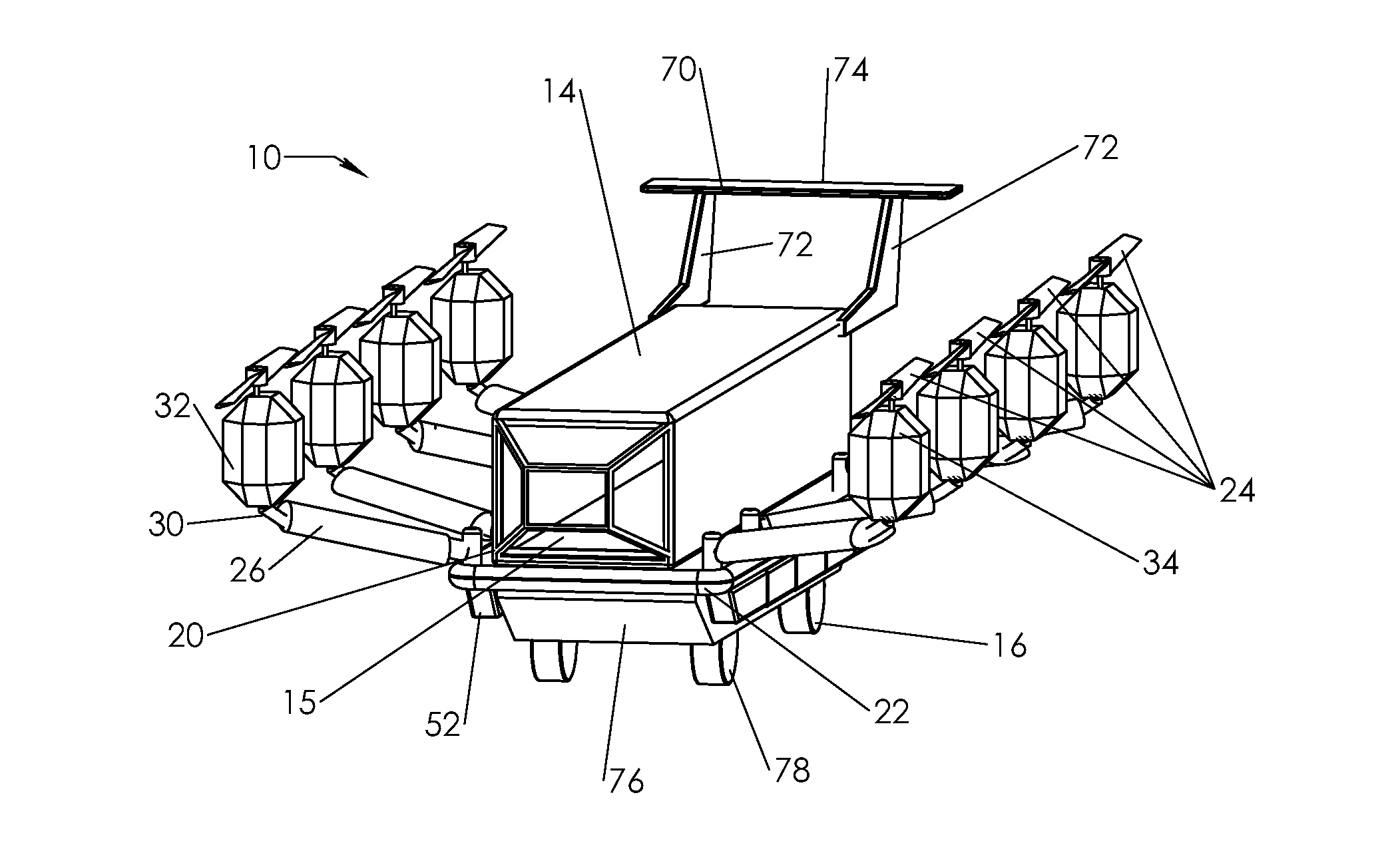
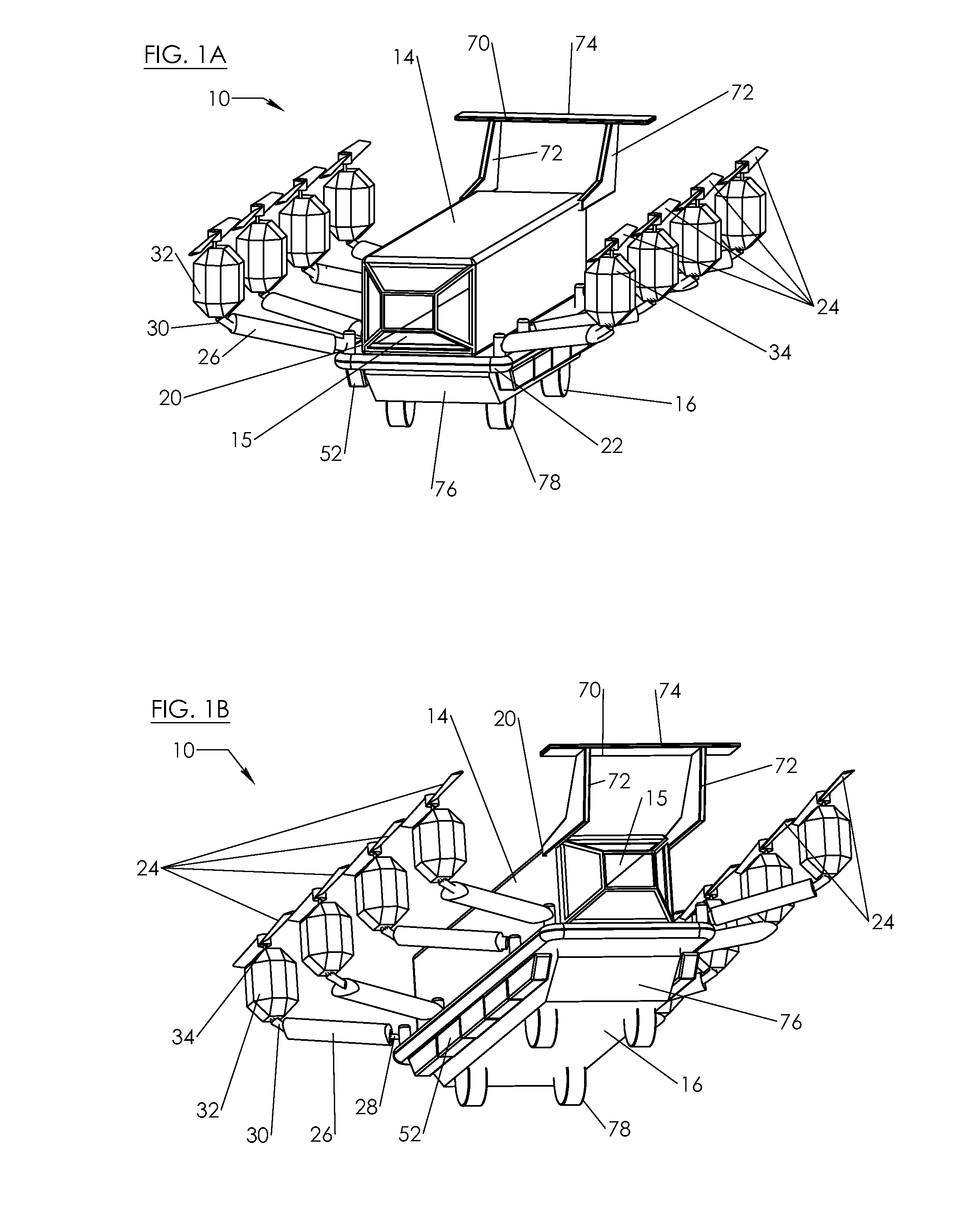
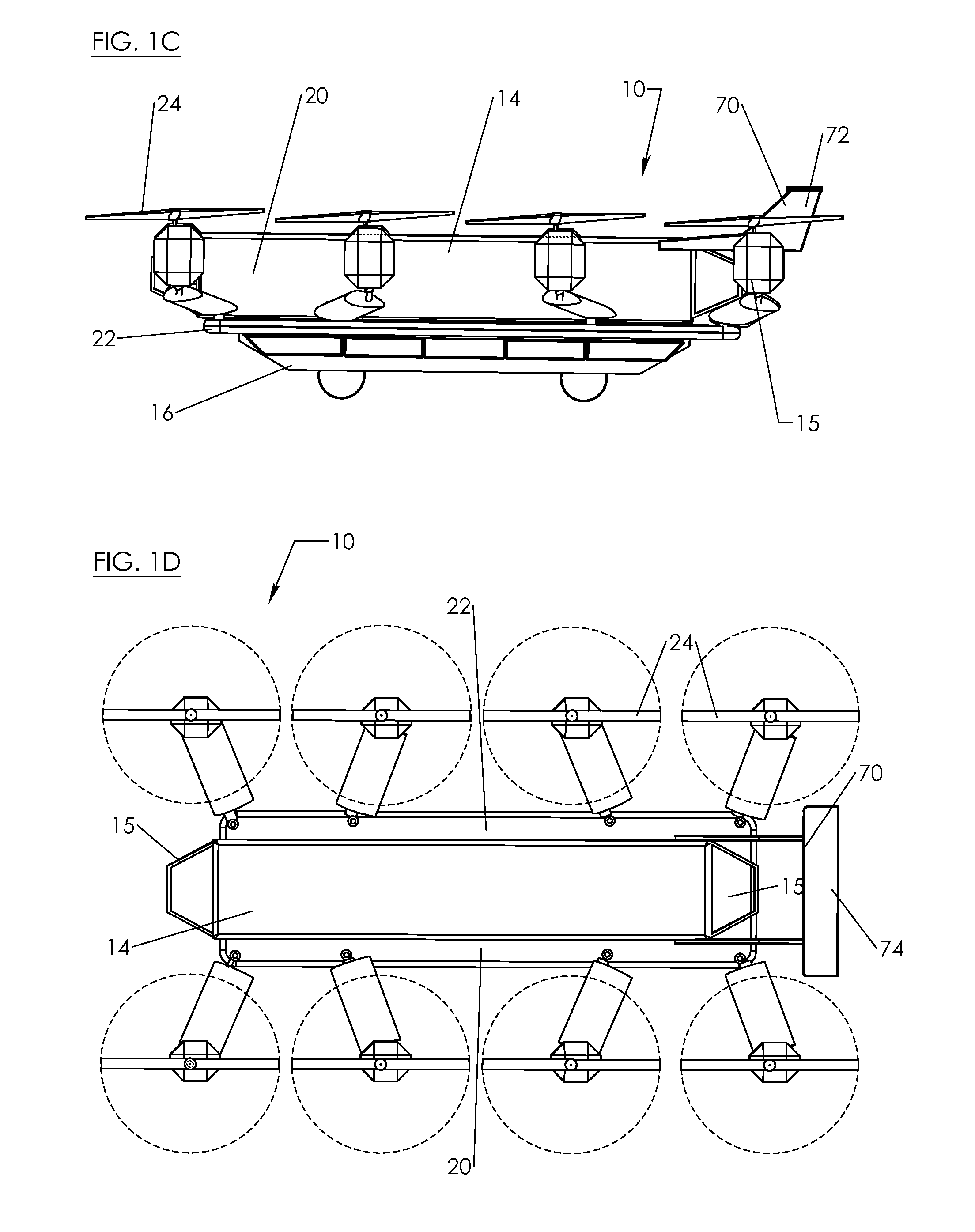
[0052]FIGS. 1A-1G depict an air vehicle 10 according to an embodiment of the invention. The air vehicle 12 includes a ground vehicle portion 16 and a flight vehicle portion 20. The flight vehicle portion 20 includes a fuselage 14 supported by a main support frame 22 having a forward axis passing through its middle in back-to-front fashion. The fuselage 14 includes front and rear canopies 15, which in the particular embodiment depicted are transparent for visibility by person(s) who may be inside the fuselage. Eight (8) propellers 24 (represented by discs representing the diameter of the circle defined by a spinning propeller) extend from the support frame 22 on propeller supports 26. Each propeller support 26 has a proximal end 28 secured to the main support frame 22, and a distal end 30. In one embodiment, each propeller support is about 6 feet in length. In the particular embodiment depicted, each propeller 24 is linked to and individually powered by a devoted engine 32, with a li...


PUM


Abstract

The invention is a modular vehicle having an air vehicle that can be coupled to cargo containers, land vehicles, sea vehicles, medical transport modules, etc. In one embodiment the air vehicle has a plurality of propellers positioned around a main airframe, which can provide vertical thrust and/or horizontal thrust. The propellers are mounted on supports which have an airfoil shape to generate additional lift. One or more of the propellers may be configured to tilt forward, backward, and/or side-to-side with respect to the airframe.

Description

RELATED APPLICATIONS[0001]The present application claims priority from U.S. Provisional Patent Application No. 61 / 332,817, filed May 10, 2010 and entitled “Modular Flying Vehicle With Airfoil,” the entire contents of which are incorporated herein by reference. The present application also relates to U.S. Provisional Patent Application No. 60 / 901,809, filed on Feb. 16, 2007, and to U.S. Utility patent application Ser. No. 12 / 070,669, filed Feb. 19, 2008, the entire contents of each of which are incorporated herein by reference.FIELD OF THE INVENTION[0002]The present invention relates to flight vehicles, and more particularly to flight vehicles configured to carry various payloads.BACKGROUND OF THE INVENTION[0003]Heavier-than-air flight vehicles have been known for that last 100 years or so, and include airplanes and helicopters. Such flight vehicles are used in many applications where speed is necessary to transport people and / or cargo to distant locations.[0004]In many applications,...

Claims


Application Information

Patent Timeline
Patent Type & Authority Applications(United States)
IPC IPC(8): B64C29/00B64C3/38B64C3/14B64C1/00
CPCB64C29/0025B64C27/20
Inventor SHAW, DONALD ORVAL
Owner SHAW DONALD ORVAL
Why Eureka
Try Eureka