Flow guide blade grid for short-distance takeoff and landing of airplane

A technology of short take-off and landing, guide vanes, applied in the direction of wing adjustment, etc., can solve the problems of unsuitability for small aircraft, high cost, and heavy weight.

Inactive Publication Date: 2014-03-12
NORTHWESTERN POLYTECHNICAL UNIV
View PDF5 Cites 0 Cited by
  • Summary
  • Abstract
  • Description
  • Claims
  • Application Information

AI Technical Summary

Problems solved by technology

[0004] In order to overcome the disadvantages of complex structure, heavy weight, high cost, and unsuitability for small aircraft in the prior art, the present invention proposes a guide vane cascade for short-distance take-off and landing of aircraft

Method used


Image

  • Flow guide blade grid for short-distance takeoff and landing of airplane
  • Flow guide blade grid for short-distance takeoff and landing of airplane
  • Flow guide blade grid for short-distance takeoff and landing of airplane

Examples


Embodiment Construction

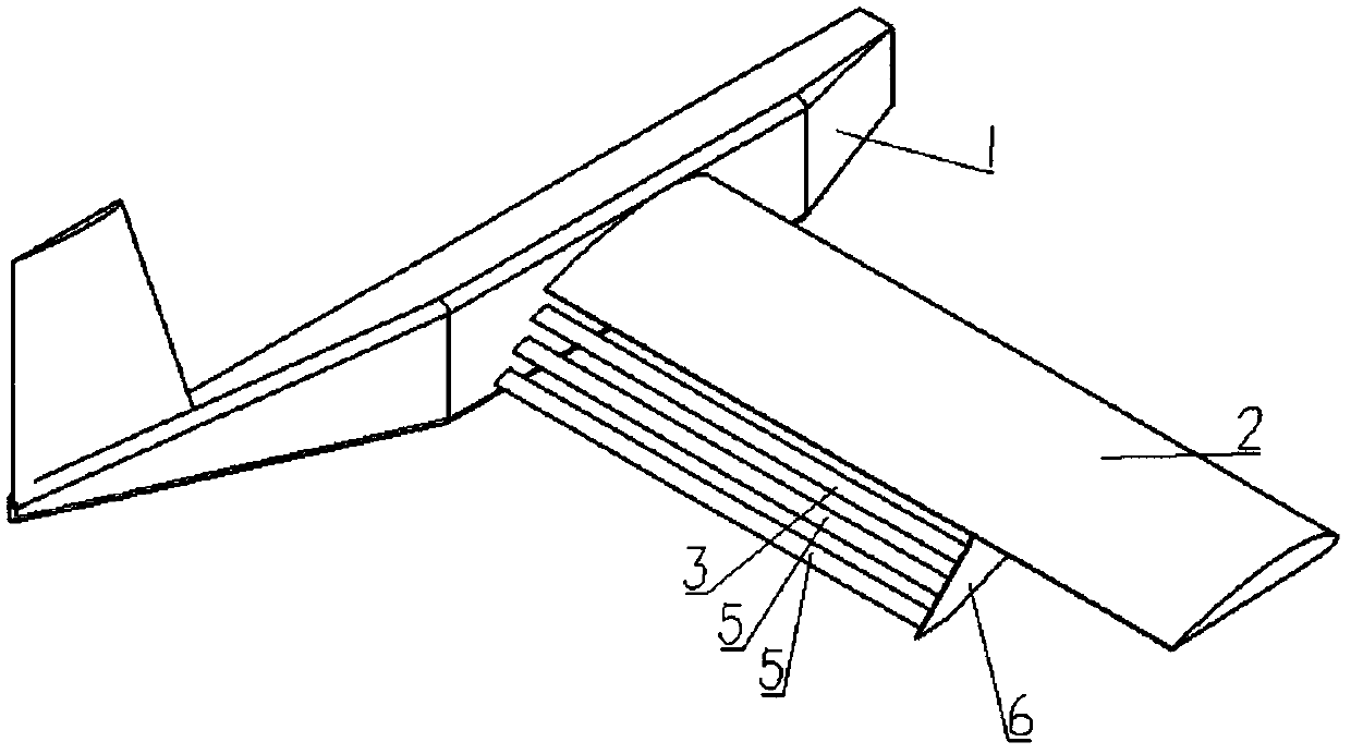
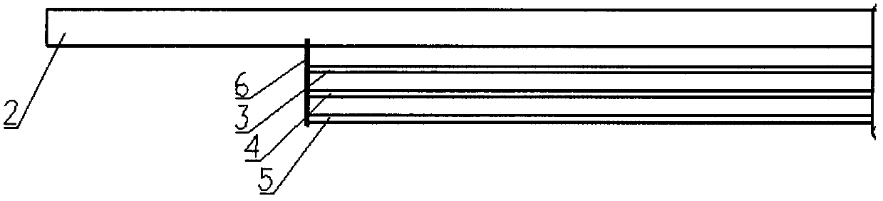
[0017] This embodiment is an aircraft short take-off and landing deflector cascade, including row wings and row wing connecting plates 6 . Described row wing comprises upper row wing 3 , middle row wing 4 and lower row wing 5 .

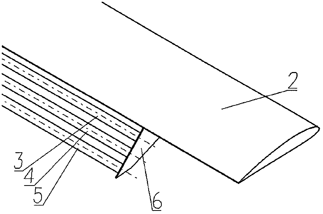
[0018] The aircraft main wing 2 of the present embodiment is a traditional straight wing, adopts NACA2413 airfoil, the wing aspect ratio is 8.85, and the installation angle relative to the fuselage is 5°. like figure 1 figure 2 As shown, the guide vane grid adopts a wing layout, and the upper wing 3, the middle wing 4 and the lower wing 5 are all NACA2310 straight wings. The chord length of the upper row wing 3, the middle row wing 4 and the lower row wing is 10% of the wing chord length, and the span length is 80% of the wing span length. like image 3 As shown, each row of wings takes the centerline of its own length direction as the axis; each row of wings deflects around its own axis, and its deflection angle is: the deflection angle of the u...


PUM


Abstract

The invention relates to a flow guide blade grid for short-distance takeoff and landing of an airplane. The chord lengths of an upper row wing, a middle row wing and a lower row wing are 10 percent of the chord length of a wing, the extension length of each row wing is 80 percent of the extension length of the wing, each row wing respectively deflects around the center line of the self length direction, the distances from the axial lines of the upper row wing, the middle row wing and the lower row wing to the front edge of the main wing in the chord direction are respectively 1.05, 1.15 and 1.25 times of the chord length of the main wing, the distances from the axial lines of the upper row wing, the middle row wing and the lower row wing to the front edge of the main wing in a direction vertical to the chord line are respectively 0.1, 0.2 and 0.3 time of the chord length of the main wing, one end of each row wing is respectively and fixedly arranged on an airplane body, the other end of each row wing is respectively and fixedly arranged on a connecting plate, and the connecting plate is fixedly arranged on the lower surface of the wing. When the flow guide blade grid is used under the wing, the airflow is guided by the blade grid, a certain retardant effect is formed on the airflow, a large-range high-pressure region is formed at the lower surface of the wing, and in addition, because the lift force effect is also realized on the three groups of row wings, the lift force of the wing is effectively improved.

Description

technical field [0001] The invention relates to the field of aerodynamic layout of aircraft, in particular to a high-lift device capable of realizing short-distance take-off and landing of aircraft. Background technique [0002] Due to the advantages of low cost, no casualties, strong survivability, and convenient use, UAVs are more and more widely used in military fields such as battlefield reconnaissance and surveillance, electronic warfare, positioning and shooting, border patrol, aviation, etc. Shooting, traffic monitoring, disaster monitoring and other civilian fields. Due to the limitation of field conditions, UAVs with short take-off and landing capabilities are often able to complete flight tasks more efficiently. [0003] At present, short take-off and landing technologies mainly include: 1. Using advanced aerodynamic layout to change the wing section and plane shape; 2. Using complex mechanical lift devices; 3. Tilting power devices; 4. Using such as jet flaps, et...

Claims


Application Information

Patent Timeline
Patent Type & Authority Patents(China)
IPC IPC(8): B64C3/58
Inventor 叶正寅杨磊周乃桢王晓朋叶坤华如豪武洁张伟伟
Owner NORTHWESTERN POLYTECHNICAL UNIV
Why Eureka
Try Eureka