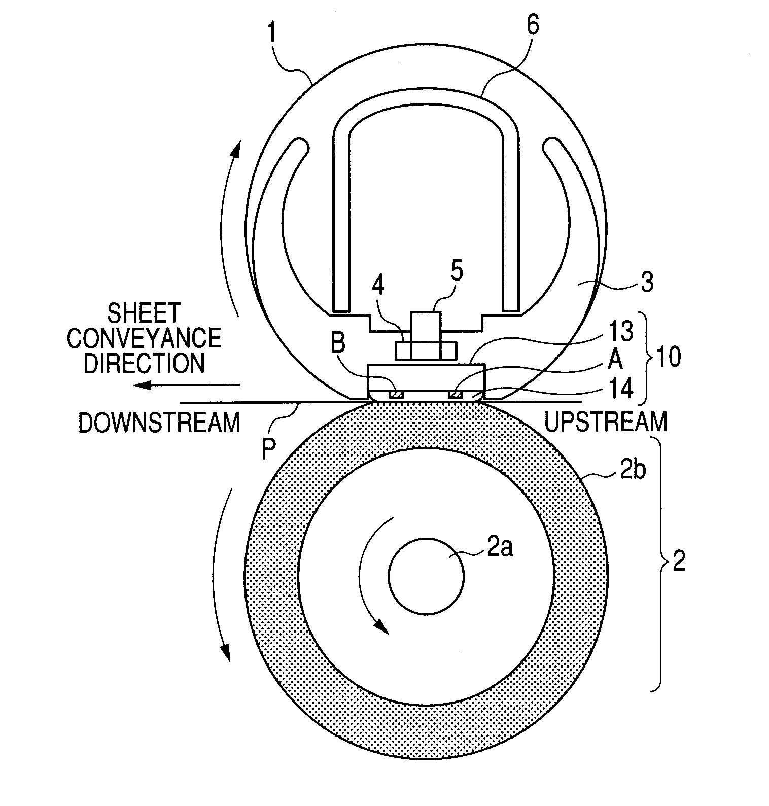
Heater, image heating device with the heater and image forming apparatus therein
a heating device and heater technology, applied in the direction of heater elements, instruments, electrographic processes, etc., can solve the problems of difficult to set the total resistance of the heat generating resistor, the material having the ptc has a very low volume resistance, and the device parts are difficult to fix. the effect of heat generation distribution unevenness in the longitudinal direction of the heater
- Summary
- Abstract
- Description
- Claims
- Application Information
AI Technical Summary
Benefits of technology
Problems solved by technology
Method used
Image
Examples
example 1
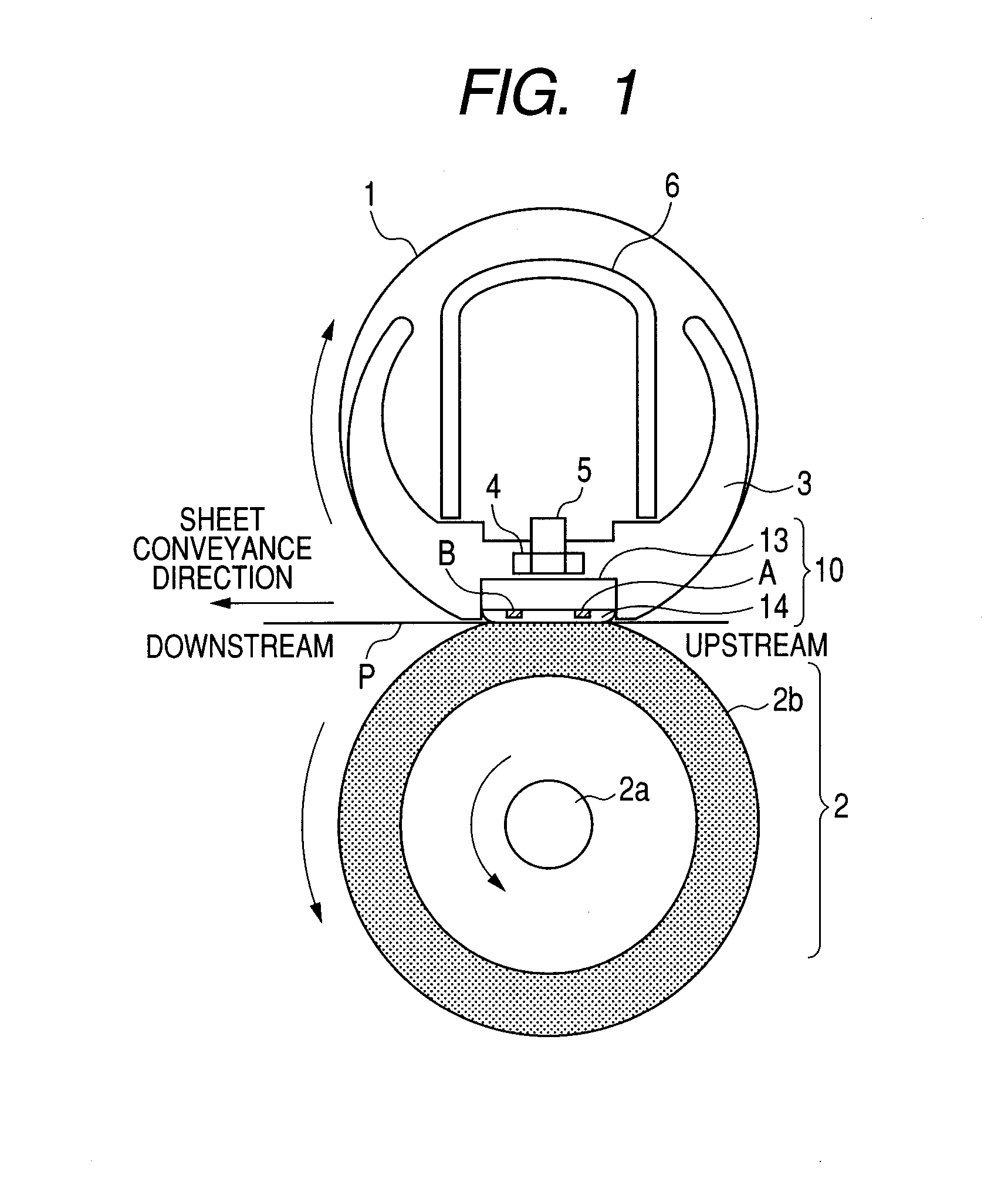
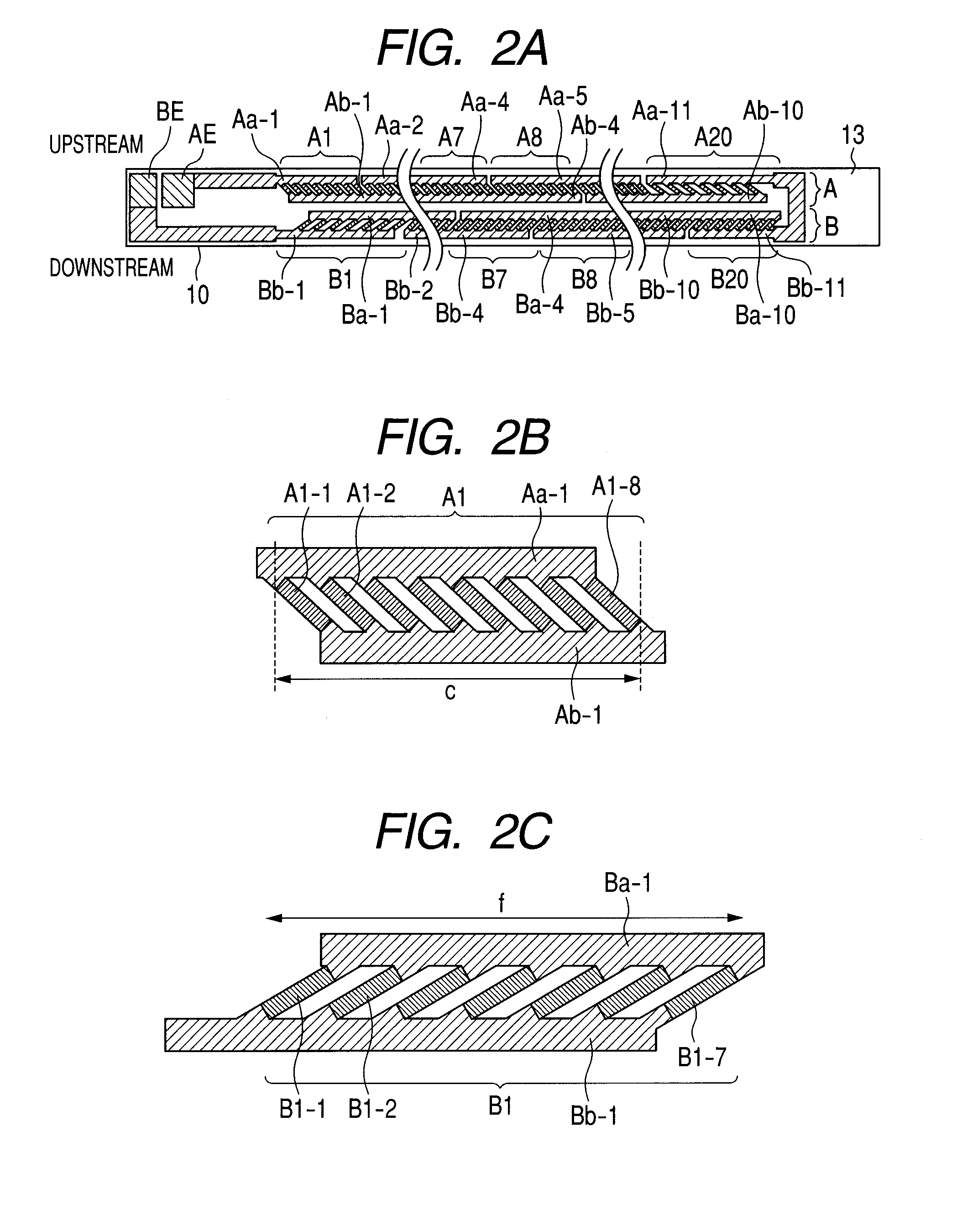
[0029]FIGS. 2A to 2C illustrate diagrams for explaining a heater structure. FIG. 2A is a front view of the heater, FIG. 2B is an enlarged view showing one heat block Al in the heat generation line A, and FIG. 2C is an enlarged view showing one heat block B1 in the heat generation line B. It is to be noted that each of the heat block A1 in the heat generation line A and the heat block B1 in the heat generation line B includes heat generating resistors each having a PTC.
[0030]The heat generation line A (the first row) includes 20 heat blocks A1 to A20, and the heat blocks A1 to A20 are connected in series. The heat generation line B (the second row) includes 20 heat blocks B1 to B20, and the heat blocks B1 to B20 are also connected in series. Moreover, the heat generation lines A and B are electrically connected in series. A power is supplied to the heat generation lines A and B from electrodes AE and BE connected to power supplying connectors.
[0031]The heat generation line A has a co...
example 2
[0046]FIG. 7 is a diagram illustrating the constitution of a heater 20 of Example 2. In the heater 20, two heater drive circuits can independently drive a heat generation line A (a first row) and a heat generation line B (a second row). Therefore, unlike the heater 10 of Example 1, an electrode CE is interconnected between the heat generation line A and the heat generation line B. A power is supplied to the heat generation line A through an electrode AE and the electrode CE, and a power is supplied to the heat generation line B through an electrode BE and the electrode CE. The heater has the same constitution as that of the heater 10 except that the electrode CE is added. Thus, the present invention can be applied to the heater having a constitution in which the heat generation lines A and B can independently be controlled.
example 3
[0047]FIGS. 8A and 8B are diagrams illustrating a constitution of a heater 30 of Example 3. As shown in FIG. 8A, heat blocks A1, A2, B1 and B2 are provided at both ends of the heater 20 along a longitudinal direction in the same manner as in the heater 10 of Example 1. Between the heat block A1 and the heat block A2 of a heat generation line A, a heat block obtained by connecting a plurality of heat generating resistors (A1-1 to Al-8 and A3-1 to A3-8) having a PTC in parallel is not provided, but a heat generation pattern AP including one heat generating resistor is connected in series with the heat blocks A1 and A2. A heat generation line B has a constitution similar to the heat generation line A. The heater 30 also obtains a uniform heat generation distribution along a substrate longitudinal direction. To this end, the heat block A1 of the heat generation line A is shifted from the heat block B1 of the heat generation line B in a heater longitudinal direction so that the block com...
PUM
 Abstract
Description
Claims
Application Information
 - R&D
- Intellectual Property
- Life Sciences
- Materials
- Tech Scout
- Unparalleled Data Quality
- Higher Quality Content
- 60% Fewer Hallucinations
Browse by: Latest US Patents, China's latest patents, Technical Efficacy Thesaurus, Application Domain, Technology Topic, Popular Technical Reports.
© 2025 PatSnap. All rights reserved.Legal|Privacy policy|Modern Slavery Act Transparency Statement|Sitemap|About US| Contact US: help@patsnap.com


