Liquid ejection printing apparatus and liquid ejection head

a printing apparatus and liquid ejection technology, applied in printing, inking apparatus, etc., can solve the problems of deteriorating image quality, uneven amount of coloring material included in the ejection droplet, and change in color concentration in ink, etc., to achieve the effect of stabilizing the flow ra

Inactive Publication Date: 2017-07-13
CANON KK
View PDF6 Cites 20 Cited by
  • Summary
  • Abstract
  • Description
  • Claims
  • Application Information

AI Technical Summary

Benefits of technology

[0009]An object of the invention is to provide a liquid ejection printing apparatus capable of stabilizing a flow rate of a liquid flowing through an ejection opening communication pass

Problems solved by technology

In this way, in a case where the differential pressure changes, a flow rate of a fluid flowing through the liquid ejection head changes and thus image quality is deteriorated.
As a result, a color concentration in the ink changes and the amount of a coloring material included in the ejected ink droplet becom

Method used


Image

  • Liquid ejection printing apparatus and liquid ejection head
  • Liquid ejection printing apparatus and liquid ejection head
  • Liquid ejection printing apparatus and liquid ejection head

Examples


first embodiment

(Description of Inkjet Printing Apparatus)

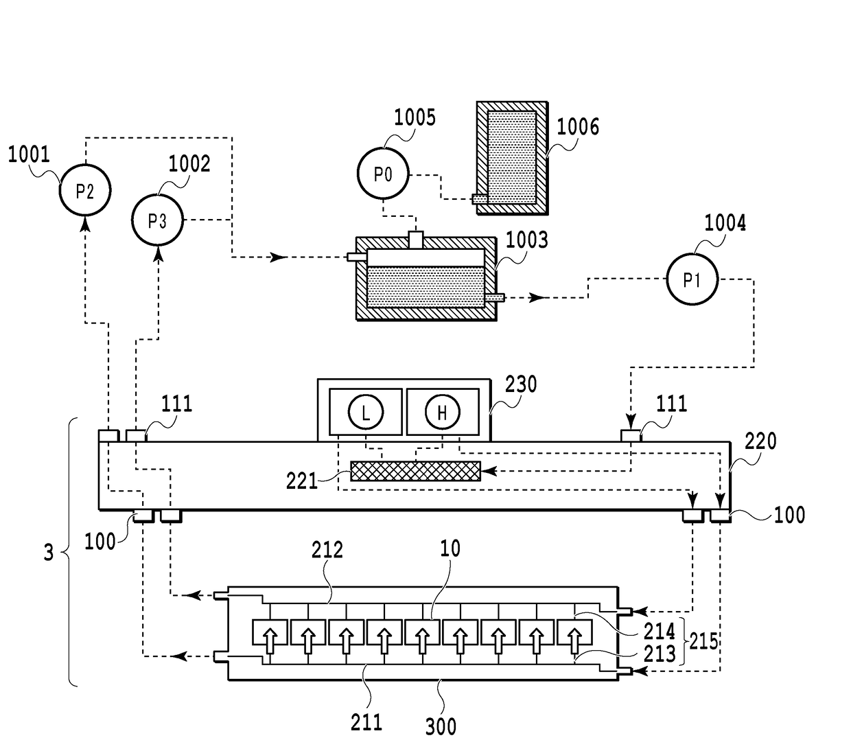
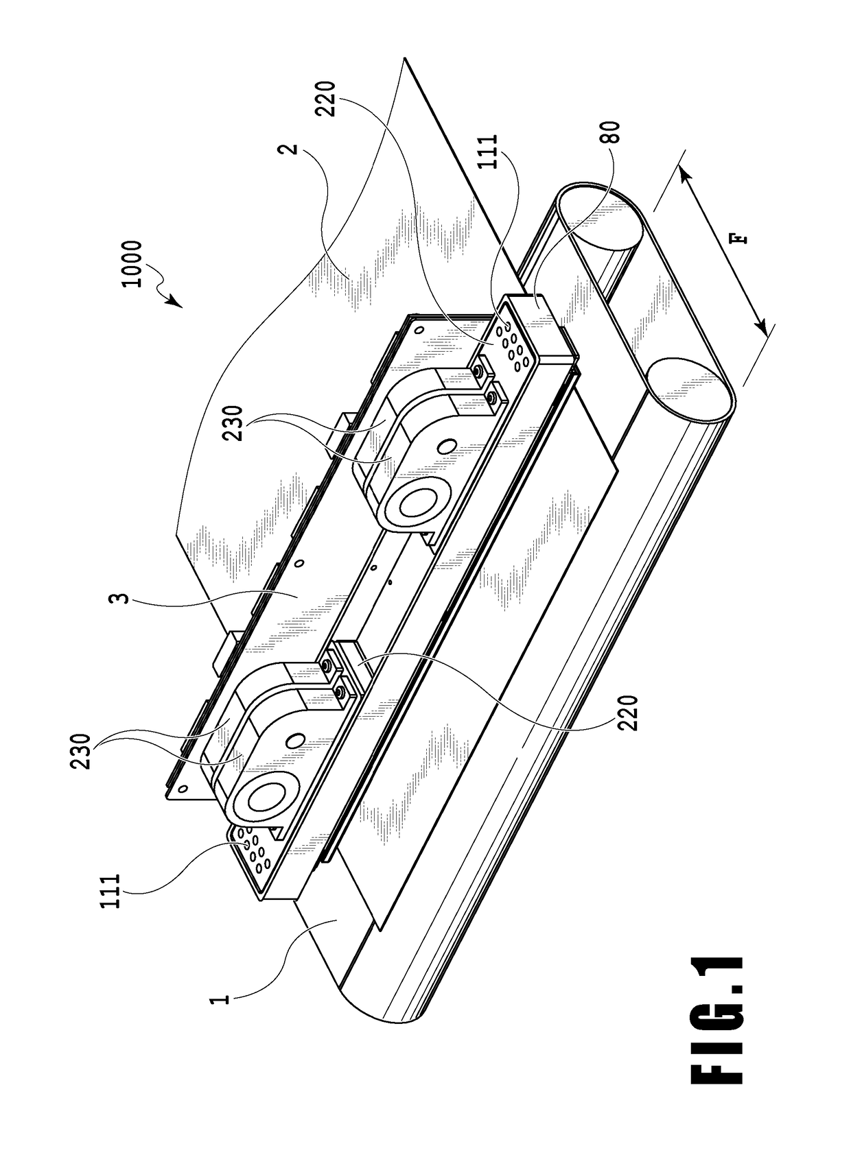
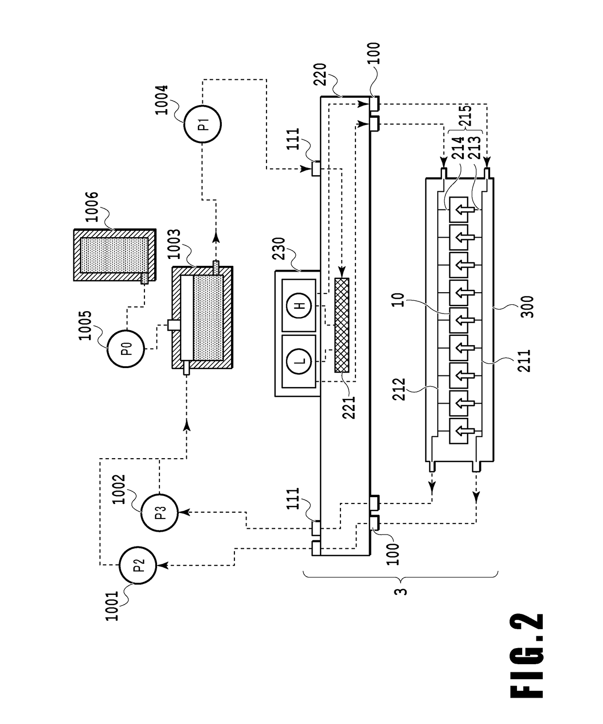
[0051]FIG. 1 is a diagram illustrating a schematic configuration of a liquid ejection apparatus that ejects a liquid in the invention and particularly an inkjet printing apparatus (hereinafter, also referred to as a printing apparatus) 1000 that prints an image by ejecting ink. The printing apparatus 1000 includes a conveying unit 1 which conveys a print medium 2 and a line type (page wide type) liquid ejection head 3 which is disposed to be substantially orthogonal to the conveying direction of the print medium 2. Then, the printing apparatus 1000 is a line type printing apparatus which continuously prints an image at one pass by ejecting ink onto the relative moving print mediums 2 while continuously or intermittently conveying the print mediums 2. The liquid ejection head 3 includes a negative pressure control unit 230 which controls a pressure (a negative pressure) inside a circulation path, a liquid supply unit 220 which communicates wi...

examples

[0112]FIG. 16 to FIGS. 22A and 22B are diagrams illustrating examples (first to eighth examples) of generating two different negative pressures in two pressure adjustment mechanisms L and H of the negative pressure control unit 230 used in the embodiment. Further, in FIG. 16 to FIGS. 22A and 22B, the same reference numerals will be given to the same components as those of FIG. 13 and FIGS. 14A and 14B and a detailed description thereof will be omitted. FIG. 16 is a diagram illustrating a negative pressure control unit 230A of the first example. The pressure control unit 230A has a configuration in which the orifice 2320 of one pressure adjustment mechanism L and the orifice 2330 of the other pressure adjustment mechanism H are disposed at different positions (heights) in the vertical direction. Reference Numeral 235 of FIG. 16 indicates a difference in height (a water head difference) between the orifice 2320 and the orifice 2330 in the vertical direction. Accordingly, the water hea...


PUM


Abstract

A liquid ejection printing apparatus includes a pressure control assembly that generates a pressure for causing the same liquid to flow to the ejection opening communication passage communicating with an ejection opening of a liquid ejection head. The pressure control assembly includes a first pressure adjustment mechanism that causes a liquid supplied from a first upstream passage to flow therefrom at a first pressure and a second pressure adjustment mechanism that causes a liquid supplied from a second upstream passage therefrom at a second pressure different from the first pressure. The first upstream passage and the second upstream passage communicate with each other and a first downstream passage communicating with the first pressure adjustment mechanism and a second downstream passage communicating with the second pressure adjustment mechanism are respectively connected to the same ejection opening communication passage communicating with the ejection opening.

Description

BACKGROUND OF THE INVENTION[0001]Field of the Invention[0002]The present invention relates to a liquid ejection printing apparatus and a liquid ejection head that print an image by ejecting a liquid from an ejection opening formed at the liquid ejection head.[0003]Description of the Related Art[0004]In a liquid ejection printing apparatus that prints an image by ejecting a liquid such as ink, there is a need to form a meniscus within an ejection opening of a liquid ejection head in a non-liquid ejection state in order to appropriately eject the liquid. For that reason, the pressures of the ejection opening and a passage communicating with the ejection opening are kept at a negative pressure by a negative pressure generation source connected to the liquid ejection head. Here, in a case where the negative pressure applied from the negative pressure generation source changes, a position of the meniscus within the ejection opening changes and thus a volume of an ejected liquid droplet a...

Claims


Application Information

Patent Timeline
IPC IPC(8): B41J2/175
CPCB41J2/17563B41J2/045B41J2/04501B41J2/14024B41J2/1404B41J2/14072B41J2/175B41J2/18B41J2202/12B41J2202/20B41J2202/21
Inventor NAGAI, NORIYASUIWANAGA, SHUZOKARITA, SEIICHIROYAMADA, KAZUHIROYAMAMOTO, AKIRAAOKI, TAKATSUNAOKUSHIMA, SHINGOSAITO, AKIOTAMENAGA, ZENTAROMORI, TATSUROU
Owner CANON KK
Why Eureka
Try Eureka