Projection apparatus and projection control apparatus

a technology of projection control and projection apparatus, which is applied in the direction of projectors, color television details, instruments, etc., can solve the problems of large apparatus size, inability to effectively and sufficiently suppress the generation of speckles, and inability to contribute to image display. , to achieve the effect of effectively suppressing the generation of brightness and color unevenness, improving the illumination intensity in the illuminated region, and effective speckles

Active Publication Date: 2014-02-13
DAI NIPPON PRINTING CO LTD
View PDF10 Cites 20 Cited by
  • Summary
  • Abstract
  • Description
  • Claims
  • Application Information

AI Technical Summary

Benefits of technology

[0019]According to the present invention, it is possible to effectively make speckles inconspicuous in an illuminated region or on an image projection surface and effectively suppress the generation of unevenness of brightness and color in the illuminated region or on the image projection surface, and also to improve the illumination intensity in the illuminated region. Moreover, by providing an intermediate optical system, it is possible to make telecentric the light modulator side of a projection optical system. Therefore, it is possible to simplify the design of a projection optical system, make the projection optical system compact, and reduce parts cost.

Problems solved by technology

As described above, with respect to projection apparatuses using a coherent light source, techniques for reducing speckles have been proposed, however, the techniques proposed so far cannot effectively and sufficiently suppress the generation of speckles.
Therefore, part of the laser beams is inevitably lost with no contribution to image display.
However, such a mechanical rotation mechanism requires a relatively large size of apparatus, and power consumption is increased.
Moreover, even if the scattering plate is rotated, the position of the optical axis of an illumination light beam is not changed, hence it is impossible to sufficiently suppress the generation of speckles caused by the diffusion on a screen.

Method used


Image

  • Projection apparatus and projection control apparatus
  • Projection apparatus and projection control apparatus
  • Projection apparatus and projection control apparatus

Examples


Embodiment Construction

[0030]Hereinafter, embodiments of the present invention will be explained with reference to the drawings. In the accompanying drawings of the present description, in order to simplify the drawings and make understanding easy, the scale, the ratio of height to width, etc., are appropriately modified or enlarged.

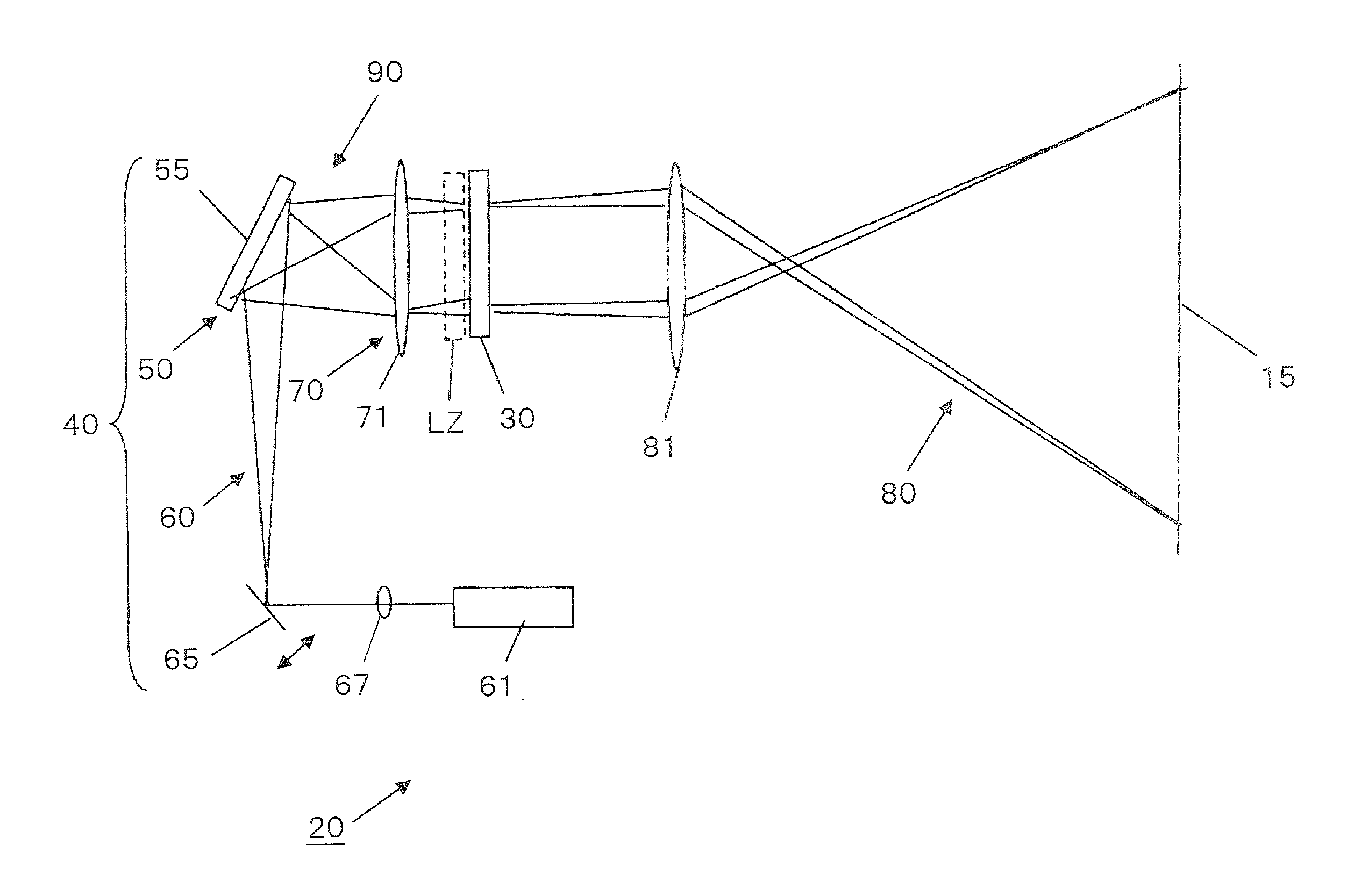
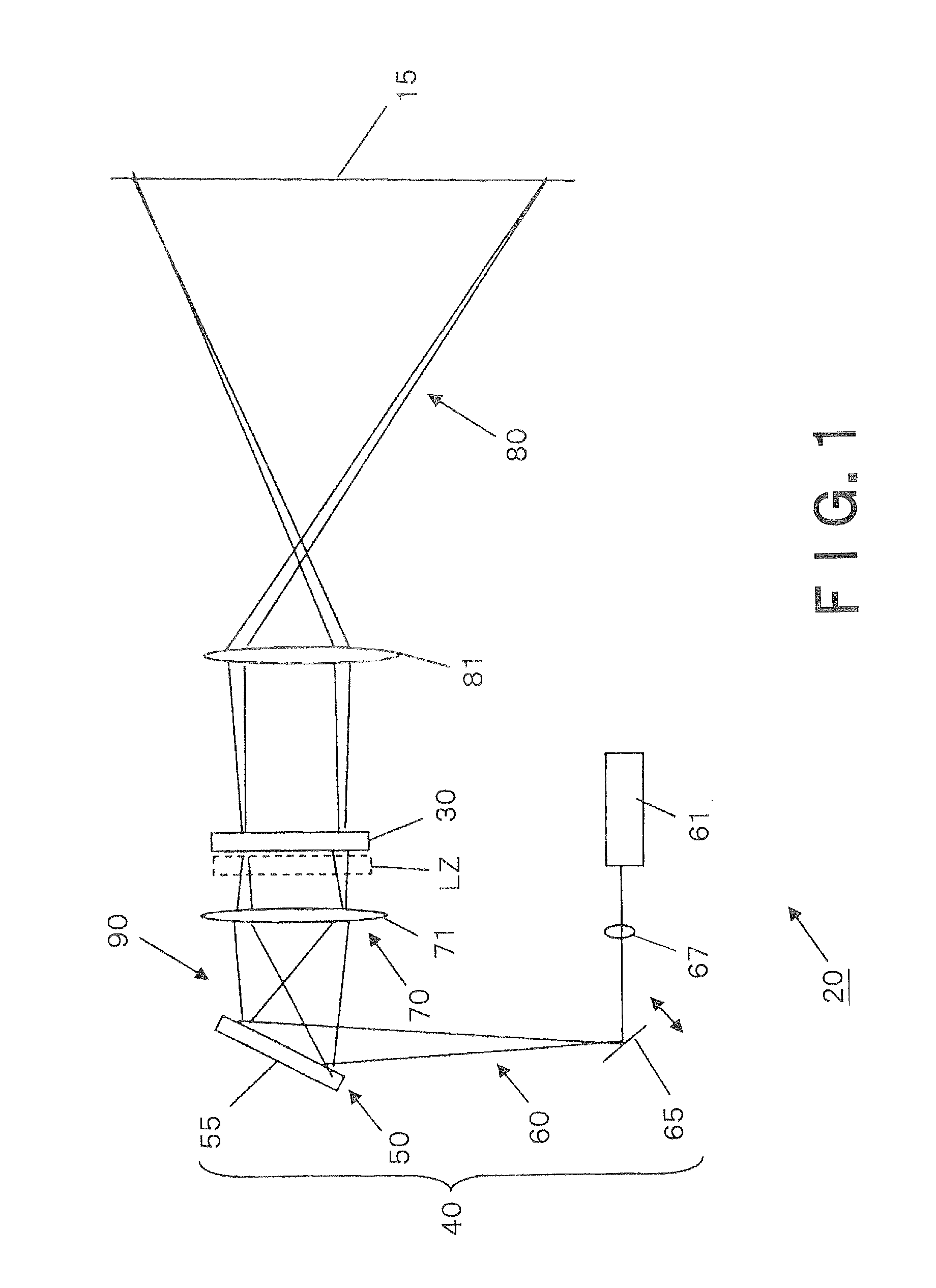
[0031]FIG. 1 is a block diagram schematically showing the configuration of a projection apparatus 20 according to an embodiment. The projection apparatus 20 of FIG. 1 is provided with an optical device 50, an irradiation unit 60, a light modulator 30, an intermediate optical system 70, and a projection optical system 80. In this specification, a device that contains the optical device 50 and the irradiation unit 60 is referred to as an illumination device 40.

[0032]The irradiation unit 60 irradiates the optical device 50 with coherent light beams so that the coherent light beams scan the surface of the optical device 50. The irradiation unit 60 has a laser source 61 that emits ...


PUM


Abstract

A projection apparatus has an optical device configured to be capable of diffusing coherent light beams, an irradiation unit configured to irradiate the coherent light beams to the optical device so that the coherent light beams scan the optical device, a light modulator that is illuminated by coherent light beams incident on and diffused at respective points of the optical device from the irradiation unit, a projection optical system configured to project a modulated image generated by the light modulator onto a scattering plane, and an intermediate optical system provided between the optical device and the light modulator, configured to restrict an diffusion angle of coherent light beams diffused by the optical device.

Description

TECHNICAL FIELD [0001]The present invention relates to a projection apparatus using a light source for emitting coherent light beams and a projection control apparatus.BACKGROUND ART[0002]Projection apparatuses that project light beams of an image onto a screen have been widely used. In a typical projection apparatus, a two-dimensional image is created as a basic image using a spatial light modulator such as a liquid crystal microdisplay or a DMD (Digital Micromirror Device), and then the two-dimensional image is magnified and projected onto a screen using a projection optical system, so that an image is displayed on the screen.[0003]As projection apparatuses, various types including a commercialized product called an “optical projector” have been proposed. In general optical projectors, a spatial light modulator such as a liquid crystal display is illuminated using an illumination device having a white light source such as a high pressure mercury lamp to obtain a modulated image, a...

Claims


Application Information

Patent Timeline
Patent Type & Authority Applications(United States)
IPC IPC(8): G03B21/14
CPCG03B21/142G02B5/32G02B27/48G03B21/2033G03B21/2066G03B21/208G03H1/32G03H2001/0439G03H2001/2292H04N9/3129G02B26/105G03H1/0402G03H1/2286G03H1/2294
Inventor KURASHIGE, MAKIOTANIGUCHI, YUKIOOOYAGI, YASUYUKI
Owner DAI NIPPON PRINTING CO LTD
Why Eureka
Try Eureka