Liquid crystal display device and substrate to be used for liquid crystal display device, and methods for producing the same

a technology of liquid crystal display and substrate, which is applied in non-linear optics, instruments, optics, etc., can solve the problems of uneven display, affecting the orientation of liquid crystal molecules in each pixel, and plastic beads spreading cannot control the position, etc., and achieves the effect of suppressing pressure-induced unevenness, good display quality and low bulging

Inactive Publication Date: 2005-12-08
SHARP KK
View PDF4 Cites 20 Cited by
  • Summary
  • Abstract
  • Description
  • Claims
  • Application Information

AI Technical Summary

Benefits of technology

[0017] In order to overcome the problems described above, preferred embodiments of the present invention provide a method for optimizing, more easily than conventionally, a configuration and distribution density of columnar spacers for obtaining a liquid crystal display device in which “low-temperature voids”, “lower bulging”, and “pressure-induced unevenness” are suppressed, and which can provide a good display quality with little unevenness in luminance associated with cell gap variations.

Problems solved by technology

However, this technique of spreading plastic beads cannot control the positions at which the spacers will be disposed, and therefore disturb the orientations of the liquid crystal molecules in each pixel.
Moreover, variations in the cell gap may occur due to the underlying protrusions and depressions of the substrate, thus causing display unevenness.
For example, if the distribution density of the columnar spacers is too high, the columnar spacers will not be able to follow the changes in thickness of the liquid crystal layer that occur due to thermal contraction and expansion of the liquid crystal material.
Thus, especially at low temperatures, “low-temperature voids” may occur.
Moreover, as schematically shown in FIG. 7, when the liquid crystal display device (liquid crystal panel) is placed in a vertical posture, the liquid crystal material will gather toward the lower part of the panel due to gravity, thus causing variations in the gap.
Among other problems, this results in unevenness in luminance (hereinafter this phenomenon will be referred to as “lower bulging”) On the other hand, if the distribution density of the columnar spacers is too small, there will not be enough mechanical strength, so that cell gap variations may occur in response to pressing of the display surface (hereinafter referred to as “pressure-induced unevenness”).
However, the inventors of the present invention conducted studies to find that the aforementioned laid-open patent publications all fail to describe necessary conditions, and, in fact, the aforementioned problems (especially “lower bulging”) cannot be sufficiently suppressed even by producing a liquid crystal display device so as to satisfy the stipulated parameter ranges.
In particular, in the case of a liquid crystal display device with a complicated configuration, if columnar spacers are formed on a structure including a resin layer (e.g., a color filter layer), it may be difficult to obtain a good display device even if the distribution density of the columnar spacers remains in the predetermined parameter ranges, depending on the physical characteristics (spring modulus) of the resin layer which is in direct or indirect contact with the columnar spacers.
Therefore, in order to determine the configuration and distribution density of the columnar spacers for obtaining a good display device, repetitive trial-and-error efforts are required.
In order to avoid trial-and-error efforts, it would be necessary to dispose the columnar spacers in a region where there is no resin layer, for example, thus resulting in limitations on the available configuration.
Furthermore, the designing methodology for the columnar spacers in the display region and the outlying peripheral region has hitherto been unclear.
There have been situations where an inappropriate columnar spacer design in the peripheral region resulted in variations in cell gap around the display region, and hence unevenness in luminance.

Method used


Image

  • Liquid crystal display device and substrate to be used for liquid crystal display device, and methods for producing the same
  • Liquid crystal display device and substrate to be used for liquid crystal display device, and methods for producing the same
  • Liquid crystal display device and substrate to be used for liquid crystal display device, and methods for producing the same

Examples


Embodiment Construction

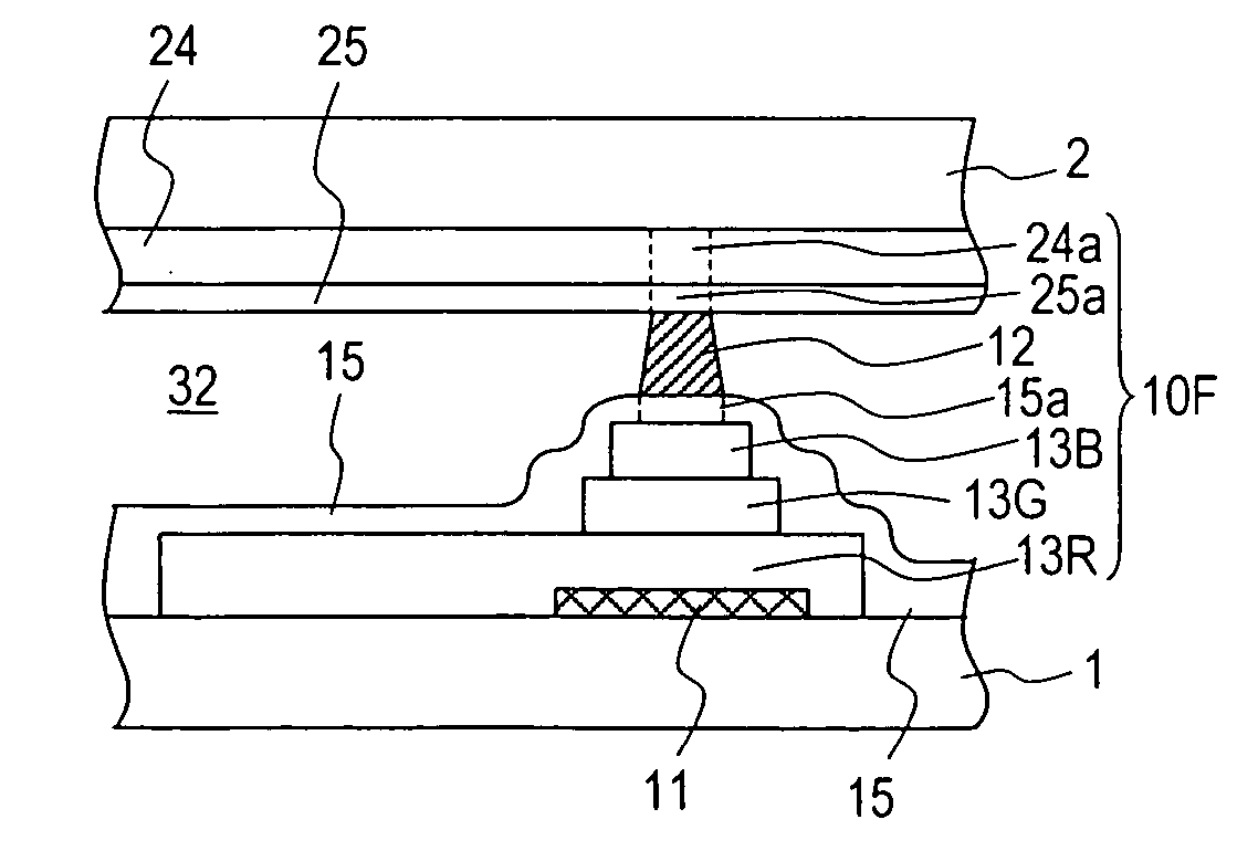
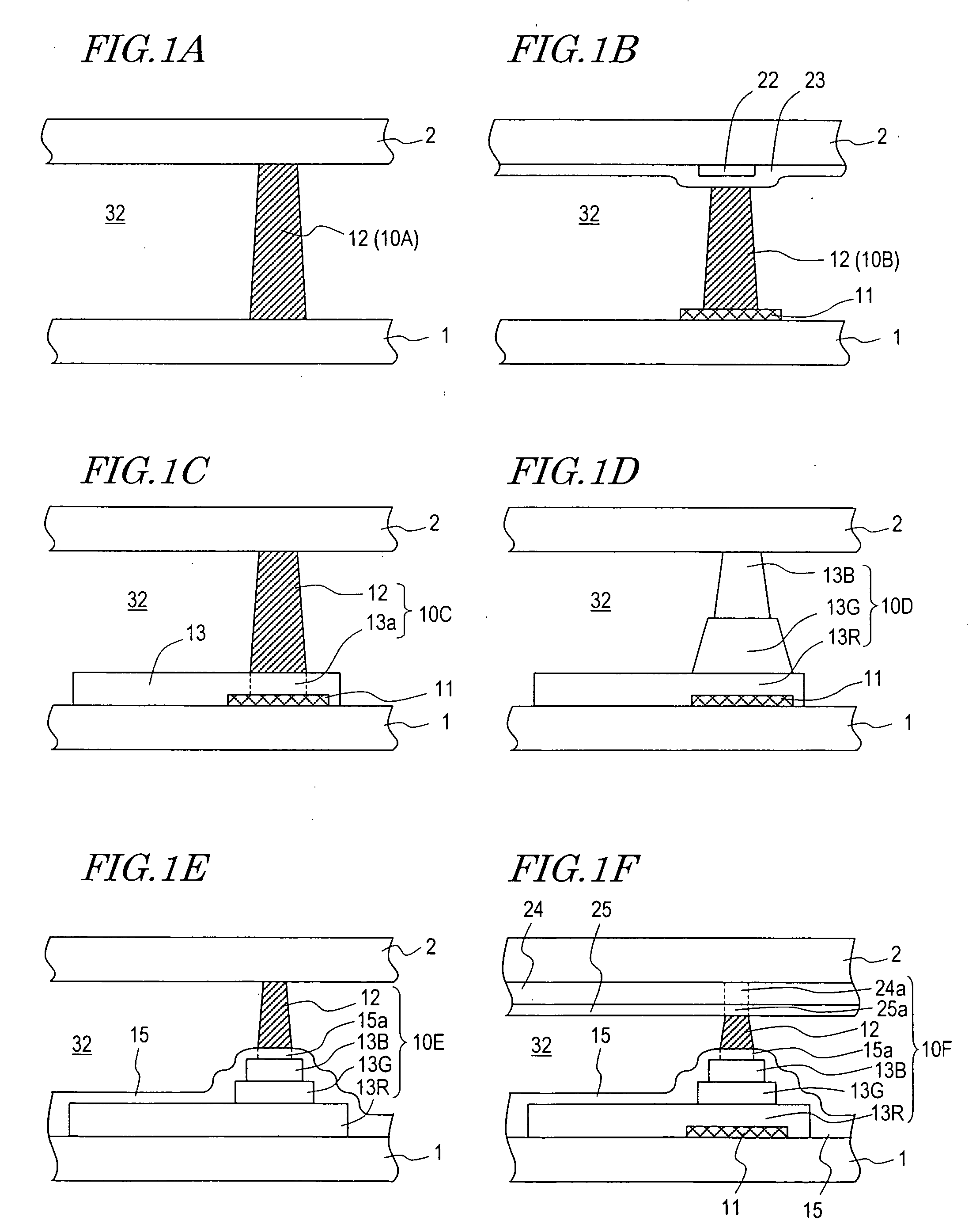
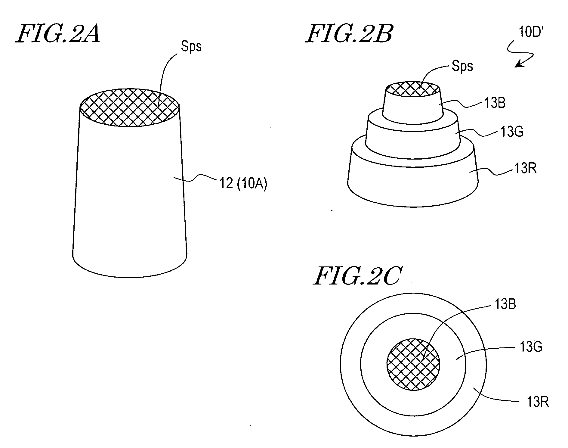
[0045] Hereinafter, a liquid crystal display device according to an embodiment of the present invention and a method for producing the same will be described with reference to the accompanying drawings. Since the method for producing a liquid crystal display device according to an embodiment of the present invention is mainly characterized by the optimization of the configuration and distribution density of columnar spacers, the configuration and distribution density of the columnar spacers will be described first.

[0046] By using various materials as described later, the inventors have conducted studies on preferable configurations and distribution densities of the columnar spacers, thus finding that, in order to suppress “low-temperature voids”, “lower bulging”, and “pressure-induced unevenness”, it is necessary for the liquid crystal display device (liquid crystal panel) to have preferable deformation characteristics. The inventors have also found that the deformation characteris...


PUM

PropertyMeasurementUnit
widthaaaaaaaaaa
temperatureaaaaaaaaaa
transmittanceaaaaaaaaaa

Abstract

It is intended to facilitate optimization of the configuration and distribution density of columnar spacers for realizing a liquid crystal display device having reduced low-temperature voids, lower bulging, and pressure-induced unevenness. A method of producing a substrate for a liquid crystal display device includes the steps of: providing a sample substrate; forming a columnar spacing structure sample on the sample substrate, the columnar spacing structure having at least one resin layer; determining a spring modulus k0(mN/μm) of the columnar spacing structure sample and a cross-sectional area Sps0 of a smallest portion of the columnar spacing structure sample, and calculating a spring modulus Kps(=k0/Sps0) of the columnar spacing structure sample per unit area; and with respect to an area S of a display region of the liquid crystal display device, a cross-sectional area Sps of a smallest portion of a columnar spacing structure to be formed on the substrate for the liquid crystal display device, and a number n of columnar spacing structures in the display region, prescribing the number n of columnar spacing structures and the cross-sectional area Sps of the smallest portion so that a spring modulus Kpt per unit area of display region, defined as Kps×(Sps×n/S), is within a range of no less than 0.00008 mN/μm3 and no more than 0.00237 mN/μm3.

Description

BACKGROUND OF THE INVENTION [0001] 1. Field of the Invention [0002] The present invention relates to a liquid crystal display device having columnar spacers, a substrate to be used therefor, and methods for producing such a liquid crystal display device and such a substrate. [0003] 2. Description of the Related Art [0004] Liquid crystal display devices are gaining higher performance as the range of their applications becomes broadened. In particular, display modes having broad viewing angle characteristics, e.g., MVA and IPS, have been developed and are receiving further improvements. [0005] In order to improve the display quality of a liquid crystal display device, it is necessary to accurately control the thickness (which may also be referred to as the “cell gap” or “cell thickness”) of the liquid crystal layer, regardless of which display mode is adopted. In particular, in large-sized liquid crystal display devices which have come into use in the recent years, it is necessary to ...

Claims


Application Information

Patent Timeline
Patent Type & Authority Applications(United States)
IPC IPC(8): G02F1/1333G02F1/1339
CPCG02F2001/133388G02F1/13394G02F1/133388G02F1/1339
Inventor YAMADA, NAOSHITSUBATA, TOSHIHIDE
Owner SHARP KK
Why Eureka
Try Eureka