Coating method for coating reaction tube prior to film forming process

a reaction tube and film forming technology, applied in the direction of coating, coating, chemical vapor deposition coating, etc., can solve the problem that the part of the reaction tube constituting the plasma generating space may not be coated in sufficient degree, and achieve the effect of preventing or restrainting contaminants

Inactive Publication Date: 2012-05-17
SHIMIZU HIRONOBU
View PDF5 Cites 323 Cited by
  • Summary
  • Abstract
  • Description
  • Claims
  • Application Information

AI Technical Summary

Benefits of technology

[0009]An object of the present invention is to provide a substrate processing apparatus and a coating method of the substrate processing apparatus which can prevent or restrain contaminants from penetrating a reaction tube and contaminating a substrate.

Problems solved by technology

However, since the inner space of the reaction tube is generally divided into the film forming space and the plasma generating space by a barrier wall, although the inner wall of the reaction tube is coated with a film, a part of the reaction tube constituting the film forming space may be mainly coated, and a part of the reaction tube constituting the plasma generating space may be insufficiently coated.

Method used


Image

  • Coating method for coating reaction tube prior to film forming process
  • Coating method for coating reaction tube prior to film forming process
  • Coating method for coating reaction tube prior to film forming process

Examples


first embodiment

[0021]In the current embodiment, the substrate processing apparatus of the present invention is configured as an example of a semiconductor manufacturing apparatus used for manufacturing semiconductor device integrated circuits (ICs). In the following description, the use of a vertical apparatus, which performs a process such as heat treatment on a substrate, will be described as an example of a substrate processing apparatus.

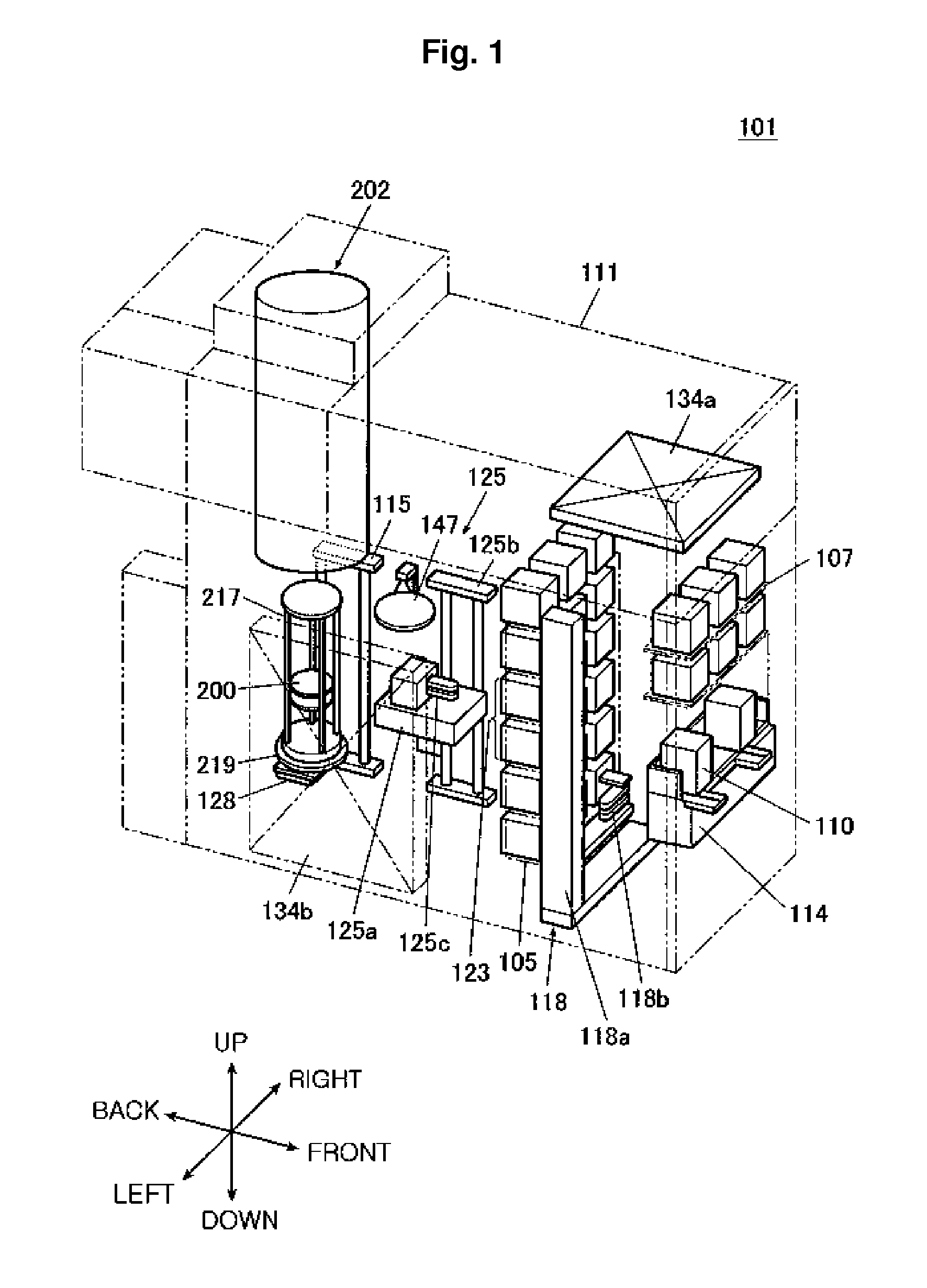
[0022]As shown in FIG. 1, in a substrate processing apparatus 101, a cassette 110 is used to store a substrate such as a wafer 200, and the wafer 200 is made of a material such as silicon. The substrate processing apparatus 101 is provided with a housing 111, in which a cassette stage 114 is installed. The cassette 110 is designed to be carried onto the cassette stage 114, or carried away from the cassette stage 114, by an in-plant carrying unit (not shown).

[0023]The cassette stage 114 is installed so that the wafer 200 maintains a vertical position inside the ...

second embodiment

[0099]The second embodiment is the same as the first embodiment in all aspects, except for those described below.

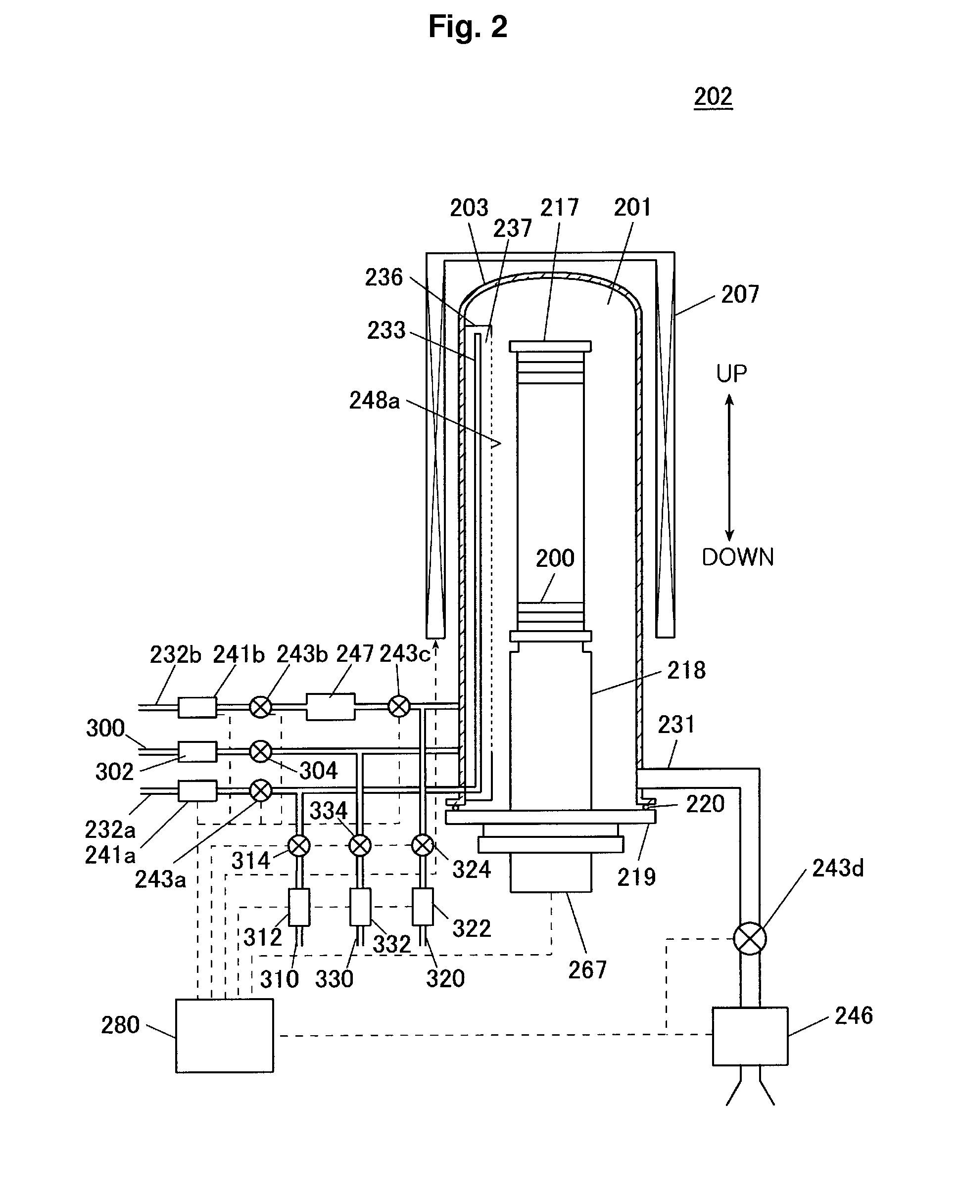
[0100]In addition to the nozzle 233 of FIG. 3, as shown in FIG. 5, a nozzle 400 is installed in the buffer chamber 237. The gas supply pipe 300 is connected to the nozzle 400. The nozzle 400 extends from the downside to the upside of the reaction tube 203 in the up-and-down direction of FIG. 2. At the nozzle 400, gas supply holes 402 are formed in the same manner as the gas supply holes 248b.

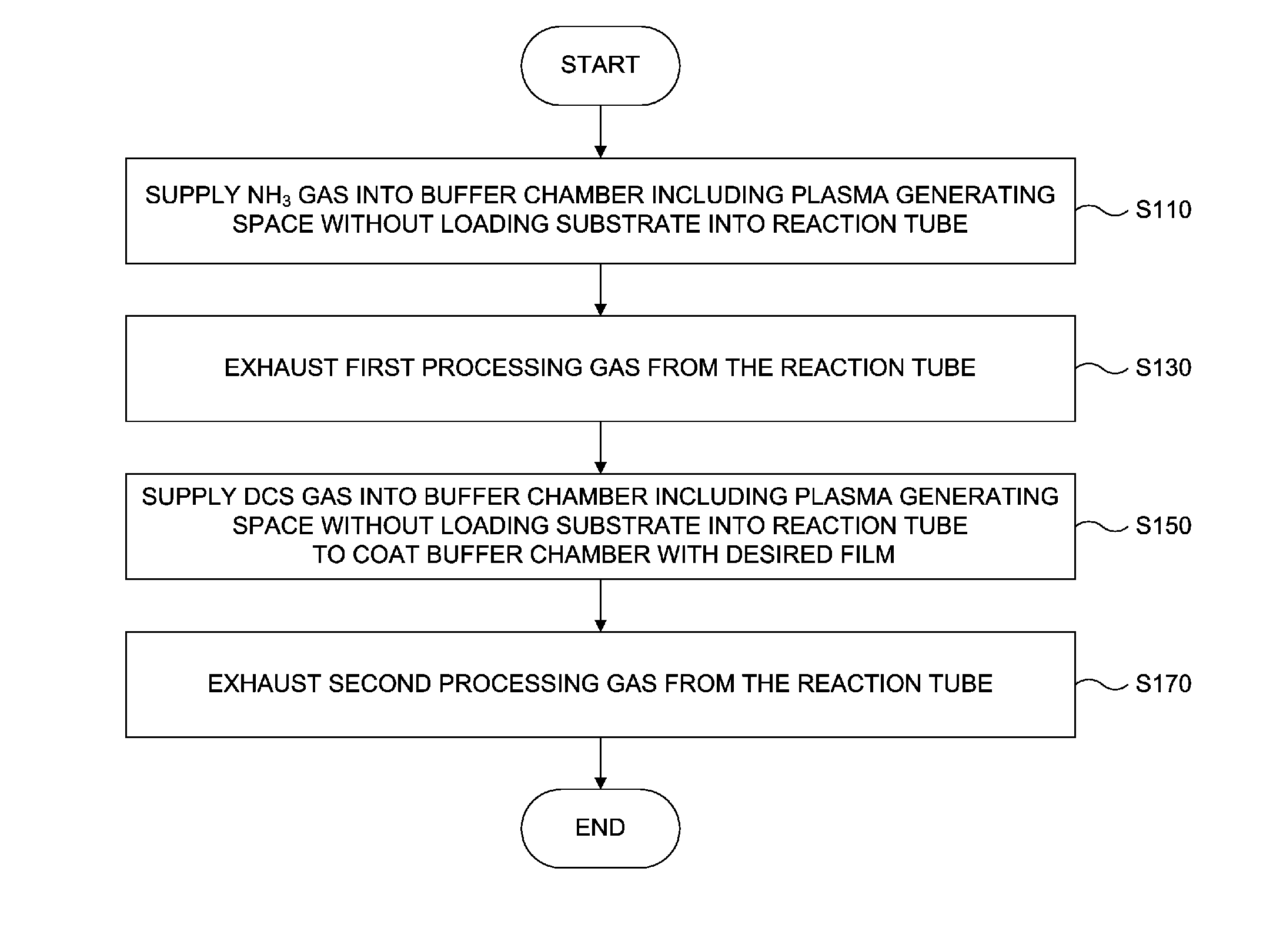
[0101]In a coating process, when DCS gas is supplied to the buffer chamber 237, the DCS gas is introduced from the gas supply pipe 300 into the nozzle 400 and is injected into the buffer chamber 237 through the gas supply holes 402 of the nozzle 400.

[0102]In the above-described embodiment, since DCS gas can be directly supplied to the buffer chamber 237, a part of the reaction tube 203 constituting the buffer chamber 237 can be coated with a Si3N4 film 500, and thus contaminants can ...

third embodiment

[0103]The third embodiment is the same as the first embodiment in all aspects, except for those described below.

[0104]Instead of the nozzle 233 of FIG. 3, as shown in FIG. 6, a nozzle 410 is installed in the buffer chamber 237. At the outside of the reaction tube 203, the nozzle 410 is divided into two parts: one is connected to the gas supply pipe 232a, and the other is connected to the gas supply pipe 300. The nozzle 410 extends from the downside to the upside of the reaction tube 203 in the up-and-down direction of FIG. 2, and gas supply holes 412 are formed in the nozzle 410 in the same manner as the gas supply holes 248b.

[0105]In a coating process, when NH3 gas is supplied to the buffer chamber 237, the NH3 gas is introduced from the gas supply pipe 232a into the nozzle 410 and is injected into the buffer chamber 237 through the gas supply holes 412 of the nozzle 410. DCS gas is supplied to the buffer chamber 237 as follows: DCS gas is introduced from the gas supply pipe 300 t...


PUM

PropertyMeasurementUnit
angleaaaaaaaaaa
temperatureaaaaaaaaaa

Abstract

Contamination of a substrate can be prevented or suppressed. A substrate processing apparatus includes a reaction tube having an inner space divided by a barrier wall into a film forming space and a plasma generating space. When a desired film is formed on a substrate placed inside the reaction tube, first and second processing gases are supplied to the reaction tube through nozzles. On the other hand, when a part of the reaction tube constituting the plasma generating space is coated with a film, second and third processing gases are supplied to the plasma generating space through the nozzle.

Description

CROSS-REFERENCE TO RELATED PATENT APPLICATIONS[0001]The present application is a Continuation-in-Part application of application Ser. No. 12 / 212,306, filed on Sep. 17, 2008; which claims priority under 35 U.S.C. §119 of Japanese Patent Application No. 2007-242630, filed on Sep. 19, 2007, in the Japanese Patent Office, the subject matter of which is also incorporated by reference herein.BACKGROUND OF THE INVENTION[0002]1. Field of the Invention[0003]The present invention relates to a substrate processing apparatus and a coating method of the substrate processing apparatus, and more particularly, to technology for preventing or suppressing penetration of a contaminant into a reaction tube in which a substrate is accommodated.[0004]2. Description of the Prior Art[0005]In a substrate processing apparatus which performs substrate processing inside a reaction tube in which a substrate is accommodated, although different kinds of processing gases may be supplied to the inside of the reacti...

Claims


Application Information

Patent Timeline
Patent Type & Authority Applications(United States)
IPC IPC(8): H01L21/31C23C16/50
CPCH01L21/67017H01L21/67109C23C16/345H01J37/3244C23C16/45542C23C16/45546C23C16/4404
Inventor SHIMIZU, HIRONOBU
Owner SHIMIZU HIRONOBU
Why Eureka
Try Eureka