Reclaimer machine

a technology of reclaimer machine and conveyor belt, which is applied in the direction of conveyors, open-pit mining, construction, etc., can solve the problem of not positioning the conveyor belt (that receives the recovery material from the stack) and achieve the effect of reducing operational downtime and cost-effective construction and manufacturing

Inactive Publication Date: 2012-06-07
VALE LIMITED
View PDF2 Cites 6 Cited by
  • Summary
  • Abstract
  • Description
  • Claims
  • Application Information

AI Technical Summary

Benefits of technology

[0008]Various aspects of the present invention include a reclaimer machine that is cost-effective in construction and manufacture, as well as providing advantages with respect to maintenance and repair throughout its life cycle, which significantly reduces operational downtime.
[0009]Aspects of this invention also provide a structurally simple reclaimer machine, capable of maintaining the required sturdiness to perform the tasks to which the reclaimer applies.
[0010]Aspects of the present invention change and simplify the conventional configurations. The construction and position of the digging and recovery systems in the machine according to aspects of the present invention allow for the free access to the digging and recovery systems because no supporting structures are needed, thus avoiding structures disposed above and / or perpendicularly inside these systems. Furthermore, the conveyor belt (that receives the recovery material from the stack) is not positioned inside and centrally to the digging and recovery systems.
[0011]In order to enable these changes, aspects of the reclaimer machine according to the present invention use a counterweight in one end, allowing the use of the support structure (bridge) only in the central part of the machine and thus eliminating the need for using the support structure to support the rotation and lateral movement of the digging and recovery sets required by the current machines. This possibility is due to the fact that in aspects of the present invention, all the support of the front part of the machine—a set of rotation, digging and recovery of material—is sustained in a balance configuration from a central axis. Therefore, such a structure also enables the use of a conveyor belt external to the set of rotation, which is longitudinal to the pile.
[0012]According to aspects of the current invention, a reclaimer machine may include a bucket wheel that includes a series of buckets rotating around a shaft, a conveyor belt connected to the bucket wheel and to a transfer chute, the conveyor belt being supported by a mobile upper platform that moves laterally towards a pile of material to be transported on tracks attached to a mobile lower platform, wherein a first end of the conveyor belt structure may be connected to the bucket wheel, and another end of the conveyor belt structure may be connected to a first counterweight that maintains the balance of the reclaimer machine and supports the bucket wheel and upper platform movements.

Problems solved by technology

Furthermore, the conveyor belt (that receives the recovery material from the stack) is not positioned inside and centrally to the digging and recovery systems.

Method used


Image

  • Reclaimer machine
  • Reclaimer machine
  • Reclaimer machine

Examples


Embodiment Construction

[0019]These and other features and advantages of this invention are described in, or are apparent from, the following detailed description of various exemplary aspects.

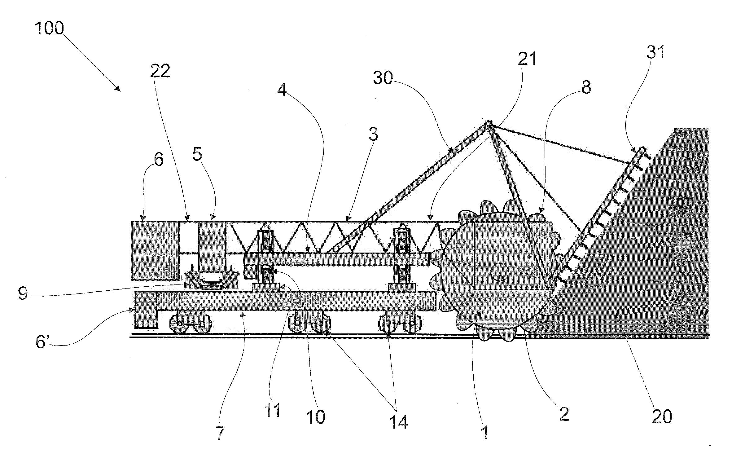
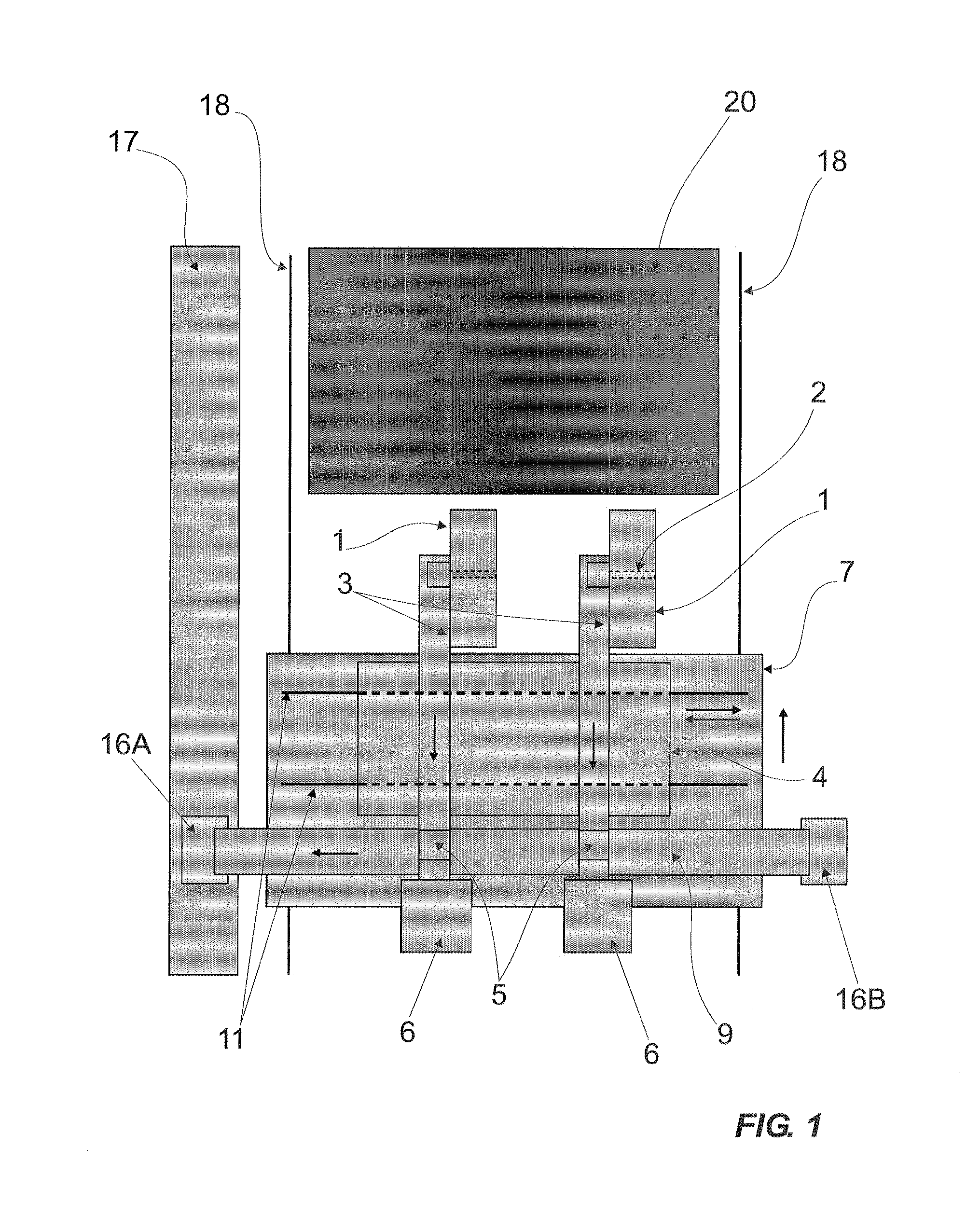
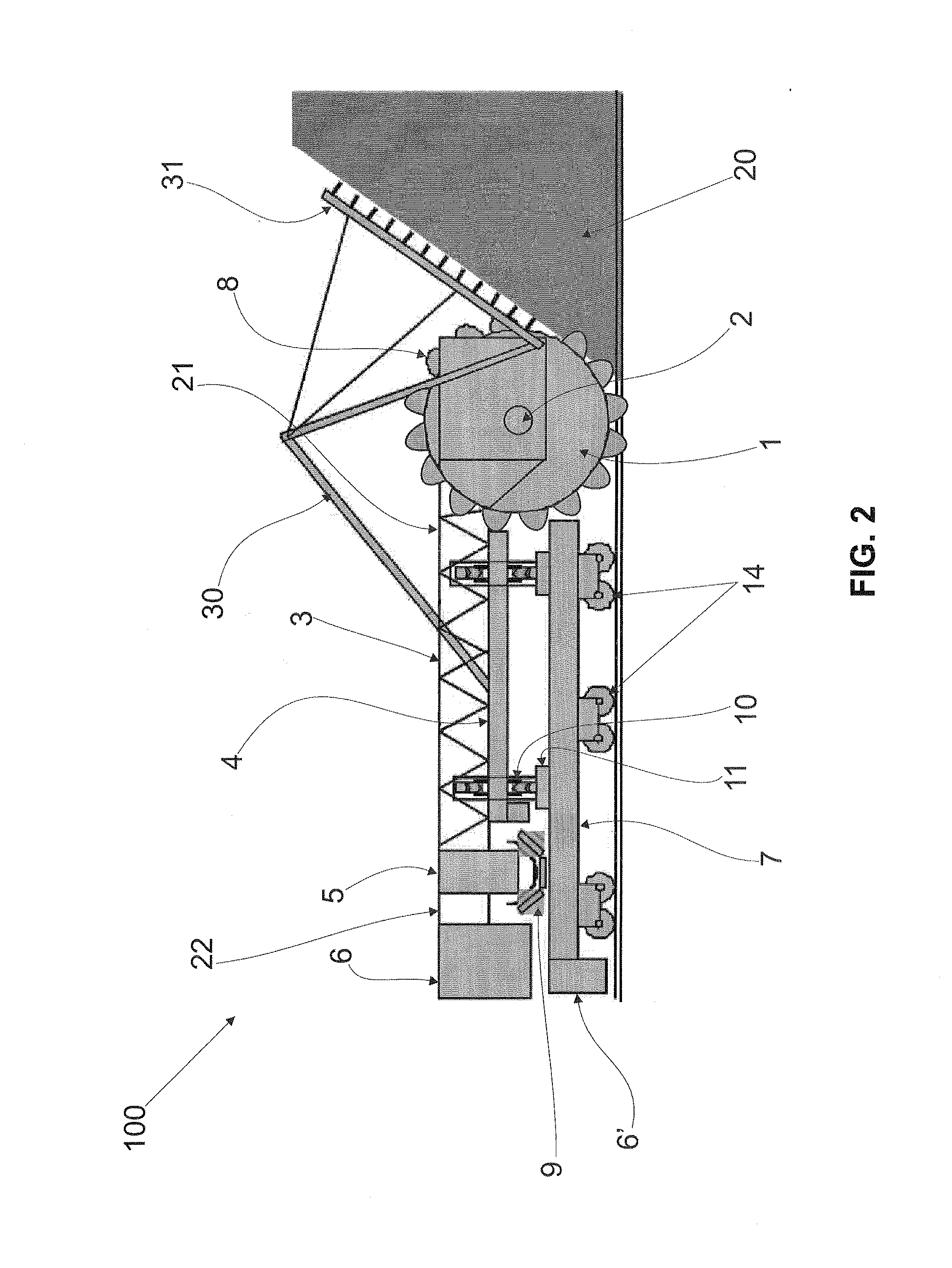
[0020]Based on the various aspects of the current invention illustrated on FIGS. 1 to 3, the reclaimer machine 100 may include a bucket wheel 1 having a series of buckets 8 rotating around a shaft 2, driven by an engine and reducer (not illustrated), or by driving force (torque), for example, from a hydraulic engine. The bucket wheel 1 may be connected to a conveyor belt structure 3, which holds the bucket wheel 1 and may also be connected to a transfer chute 5.

[0021]FIG. 1 is a schematic view of a reclaimer machine according to various aspects of the current invention, and FIG. 2 is a side view of an aspect of a reclaimer machine according to various aspects of the current invention. A rake-type supporting structure 30 may be connected to the conveyor belt structure 3 which holds a counterweight 6. This structure 30 ...


PUM


Abstract

Aspects of this invention include a reclaimer machine for reclaiming and homogenizing materials such as ore, coal and others, stock-piled in yards. The reclaimer machine may include a bucket wheel having a series of buckets rotating around a shaft, a conveyor belt connected to the bucket wheel and to a transfer chute, the conveyor belt being supported by a mobile upper platform that moves laterally to a pile on tracks attached to a mobile lower platform, wherein a first end of the conveyor belt structure may be connected to the bucket wheel and another end of the conveyor belt structure may be connected to a counterweight which maintains the balance of the reclaimer machine and supports the bucket wheel, upper platform and lower platform movements.

Description

BACKGROUND OF THE INVENTION[0001]1. Field of Invention[0002]Aspects of the present invention relate to a reclaimer machine for reclaiming and homogenizing materials such as ore, coal and others, either stocked or accumulated in yards.[0003]2. Description of Related Art[0004]The machines currently available for reclaiming and homogenizing materials from stacks in storage yards are generally divided into two models: bridge reclaimer with bucket wheels, and drum reclaimer.[0005]The bridge reclaimer with wheels and bucket is generally divided into three sets: (a) feed system on the stack, (b) system of lateral movement of the bucket wheels and rake and (c) turning system for digging and recovery of stack material. The dynamics of the operation is due by the synchronization of the feed, lateral and turning movement of these sets. As a result of the synchronized movements of these sets, the digging and recovery material from the stack is discharged in the center of the wheel, where there ...

Claims


Application Information

Patent Timeline
Patent Type & Authority Applications(United States)
IPC IPC(8): B65G65/06
CPCE02F3/181E02F9/18E02F7/06E02F3/188E21C47/02
Inventor CRUZ, MARCELO M.
Owner VALE LIMITED
Why Eureka
Try Eureka