Hydraulic ground propulsion system

a ground propulsion and hydraulic technology, applied in the direction of wheel arrangements, alighting gear, transportation and packaging, etc., can solve the problems of inefficiency of aircraft engine taxiing, affecting the safety of ground personnel, and dependence on ground suppor

Inactive Publication Date: 2012-06-07
BAE SYSTEMS CONTROLS INC
View PDF27 Cites 30 Cited by
  • Summary
  • Abstract
  • Description
  • Claims
  • Application Information

AI Technical Summary

Benefits of technology

[0015]The hydraulic system further comprises a first temperature control system for cooling the hydraulic fluid and pressurized hydraulic fluid based upon a control signal from the controller.
[0016]The first temperature control system can be a forced air cooling device.
[0017]The ground propulsion system further comprises a second temperature control system for heating the hydraulic fluid when a tempera

Problems solved by technology

However, using the aircraft engines for taxi is inefficient and poses safety risk to ground personal.
However, the use of a towbar/wheel tug for push back and maneuvering creates a dependence on ground support personal and equipment.
Additionally, the aircraft must carry additional weight in

Method used


Image

  • Hydraulic ground propulsion system
  • Hydraulic ground propulsion system
  • Hydraulic ground propulsion system

Examples


Embodiment Construction

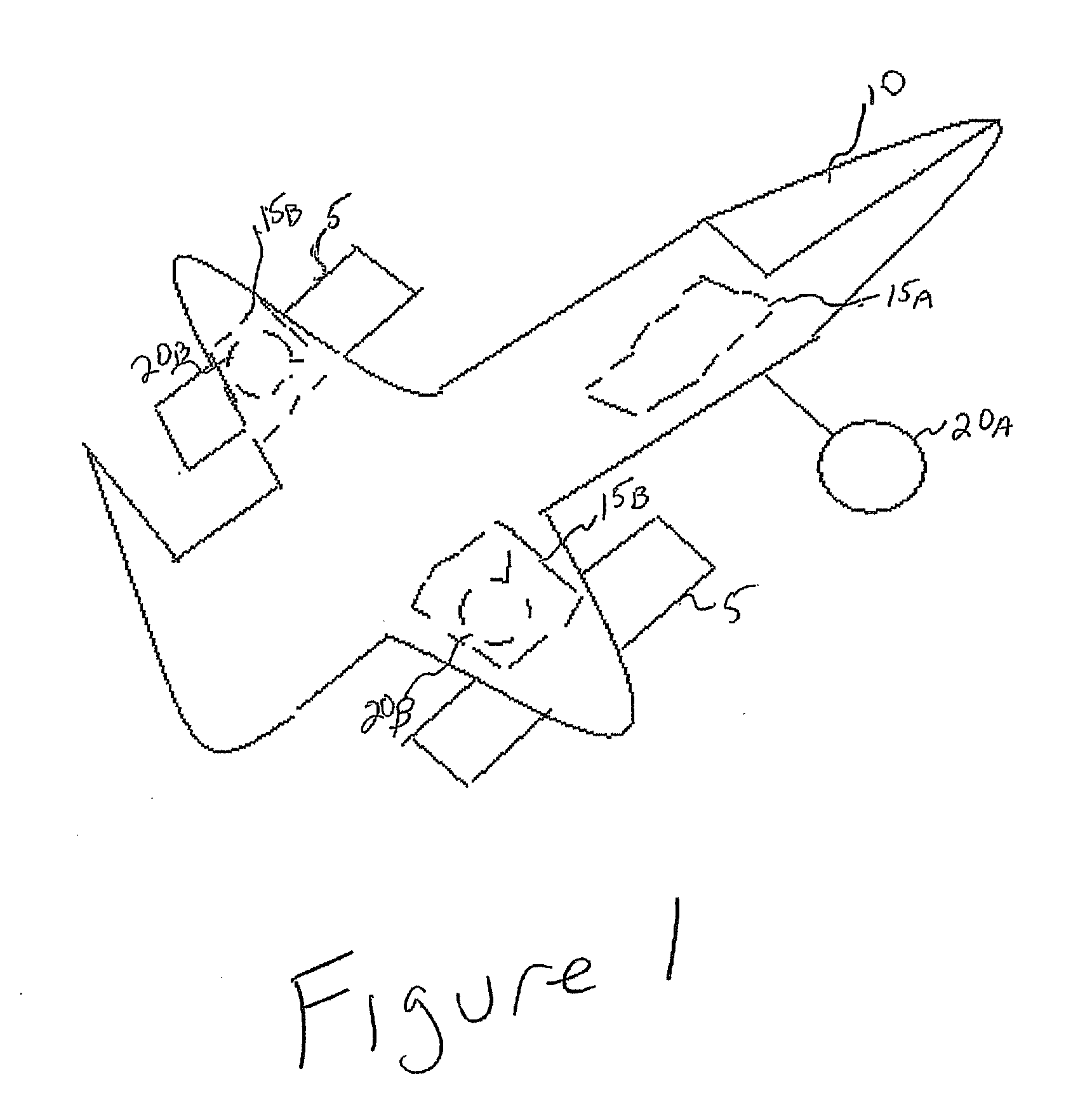
[0032]FIG. 1 illustrates an aircraft 1. The aircraft 1 has three sets of wheels for taxiing, takeoff and landing: a nose gear 20A and two rear / main gears 20B (collectively “wheel assemblies”). For purposes of the description the wheel assemblies will be described as wheel assembly 15. During landing the wheel assemblies 20A and 20B are extended from the landing gear bay 15A and 15B, respectively. The extension of the wheel assemblies 20A and 20B are controlled by the pilot in the cockpit 10. The main engines 5 are used to propel the aircraft 1 during takeoff. However, during taxi a hydraulic ground propulsion system as described herein is used to control the speed and torque of the axel / wheels.

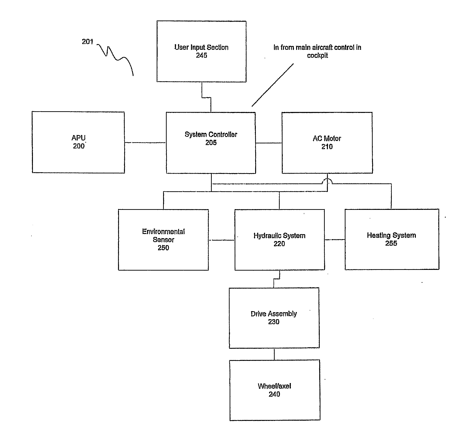
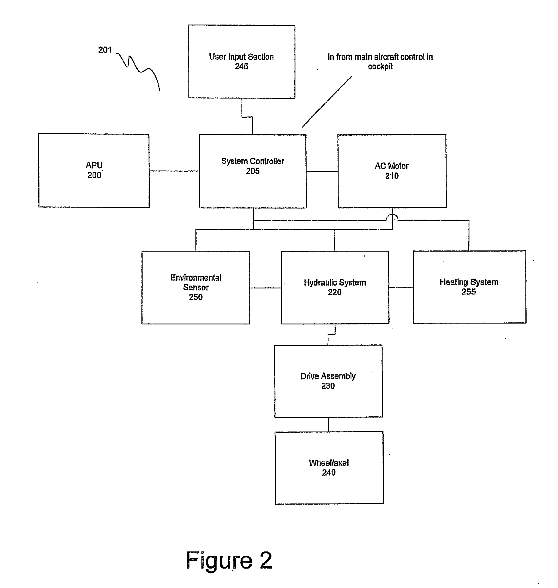
[0033]FIG. 2 illustrates a block diagram of the hydraulic ground propulsion system 201 according to the invention. The hydraulic ground propulsion system 201 can be included in the nose gear 20A and / or both of the rear / main gears 20B. The hydraulic ground propulsion system 201 has a system con...


PUM


Abstract

A hydraulic ground propulsion system for an aircraft. The system comprises a wheel, axel, an aircraft power interface device, an electric motor, a hydraulic system, a drive assembly and a controller. The wheel is rotatably coupled to the wheel axel. The aircraft power interface device interfaces an aircraft power source. The electric motor is coupled to the aircraft power interface device and receives power from the aircraft power source through the aircraft power interface device. The hydraulic system is driven by the electric motor. The drive assembly mechanically couples the wheel axel to the hydraulic system. The drive assembly is mechanically driven by the hydraulic system. The drive assembly transfers energy from the hydraulic system to the wheel axel. The controller controls the electric motor and the hydraulic system based upon a pilot torque command.

Description

FIELD OF THE INVENTION[0001]This invention relates to an aircraft ground propulsion system. More particularly, the invention relates a hydraulic ground propulsion system.BACKGROUND[0002]During taxi an aircraft uses a ground propulsion system to control the speed and torque of landing gear axels and wheels. Typically, aircraft engines are used for propulsion power. However, using the aircraft engines for taxi is inefficient and poses safety risk to ground personal. Alternatively, a towbar / wheel tug can be used. However, the use of a towbar / wheel tug for push back and maneuvering creates a dependence on ground support personal and equipment. Additionally, the aircraft must carry additional weight in the towbar when operating between remote runways. The towbars can weigh up to several hundreds of pounds.[0003]Another alternative is the use of one or more high powered electric motors to propel the aircraft for taxi. These electric motors require liquid jacket cooling to avoid exceeding ...

Claims


Application Information

Patent Timeline
IPC IPC(8): B64C25/34B64C25/36
CPCY02T50/823B64C25/405Y02T50/80
Inventor HISSONG, ERIN T.
Owner BAE SYSTEMS CONTROLS INC
Why Eureka
Try Eureka