
Harvester header

a head and head technology, applied in the field of head and head, can solve problems such as problems such as the possibility of feeding the crop into the head and auger

Inactive Publication Date: 2011-08-04
GUYER WAYNE A
View PDF14 Cites 4 Cited by
  • Summary
  • Abstract
  • Description
  • Claims
  • Application Information

AI Technical Summary

Benefits of technology

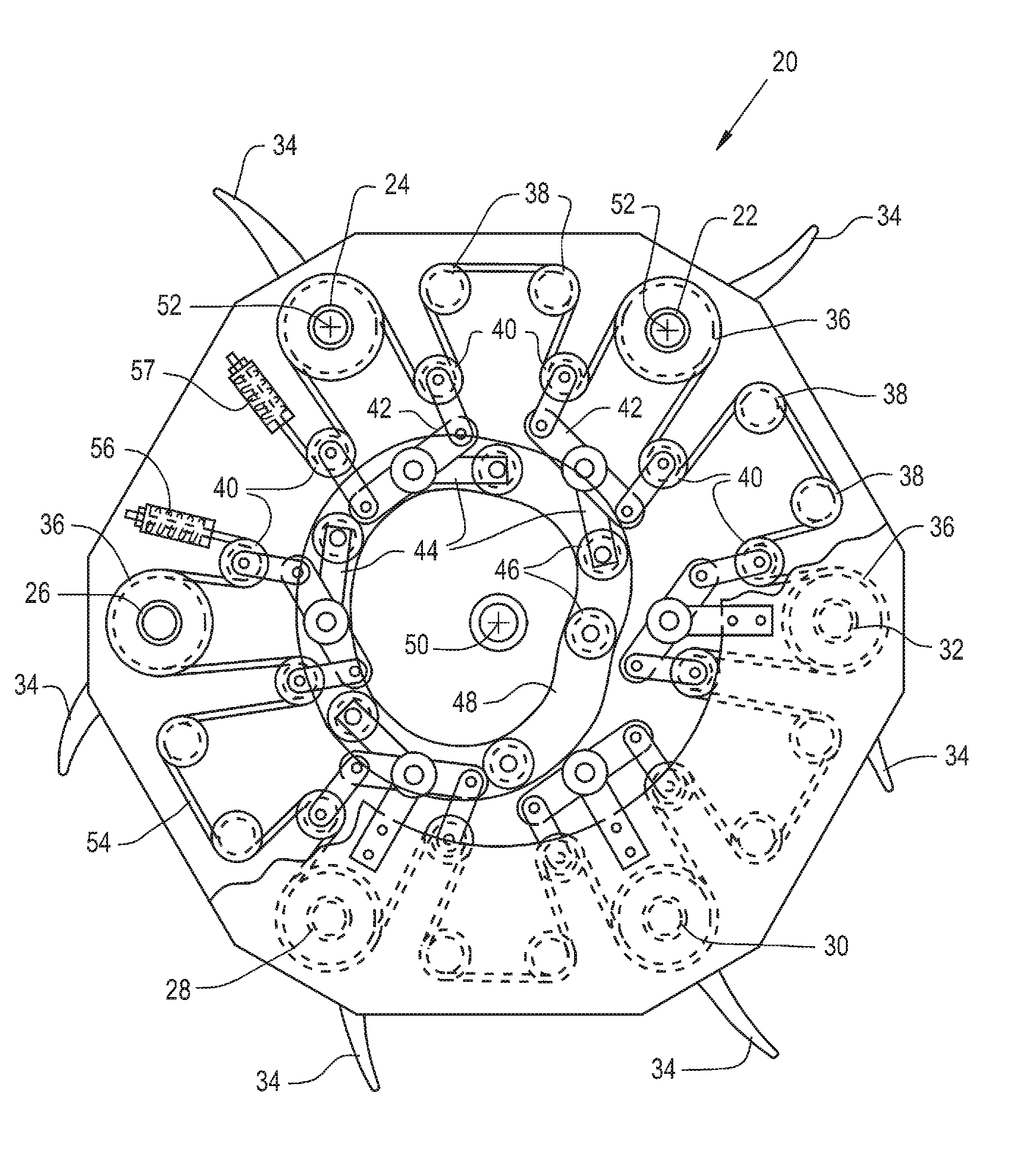
"The present invention is about a reel bat drive for a harvester. It includes a chassis, a header, and a bat reel assembly. The bat reel assembly has a reel structural assembly, a plurality of bat rods, a tensioned member, and a moveable pivotal member. The tensioned member is connected to the bat rods and the moveable pivotal member is located between the first and second bat rods. The invention has the advantage of adjusting the drive path for each bat rod and using only one tensioned member to drive all six bats, although each bat is individually driven."

Problems solved by technology

Depending upon the crop size, the moisture of the crop, and the cutting conditions, feeding the crop into the auger may present problems.

Method used


Image

  • Harvester header
  • Harvester header
  • Harvester header

Examples


Embodiment Construction

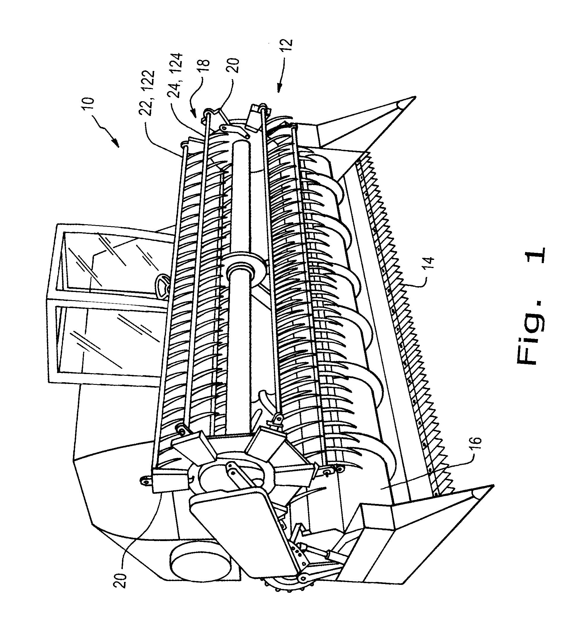
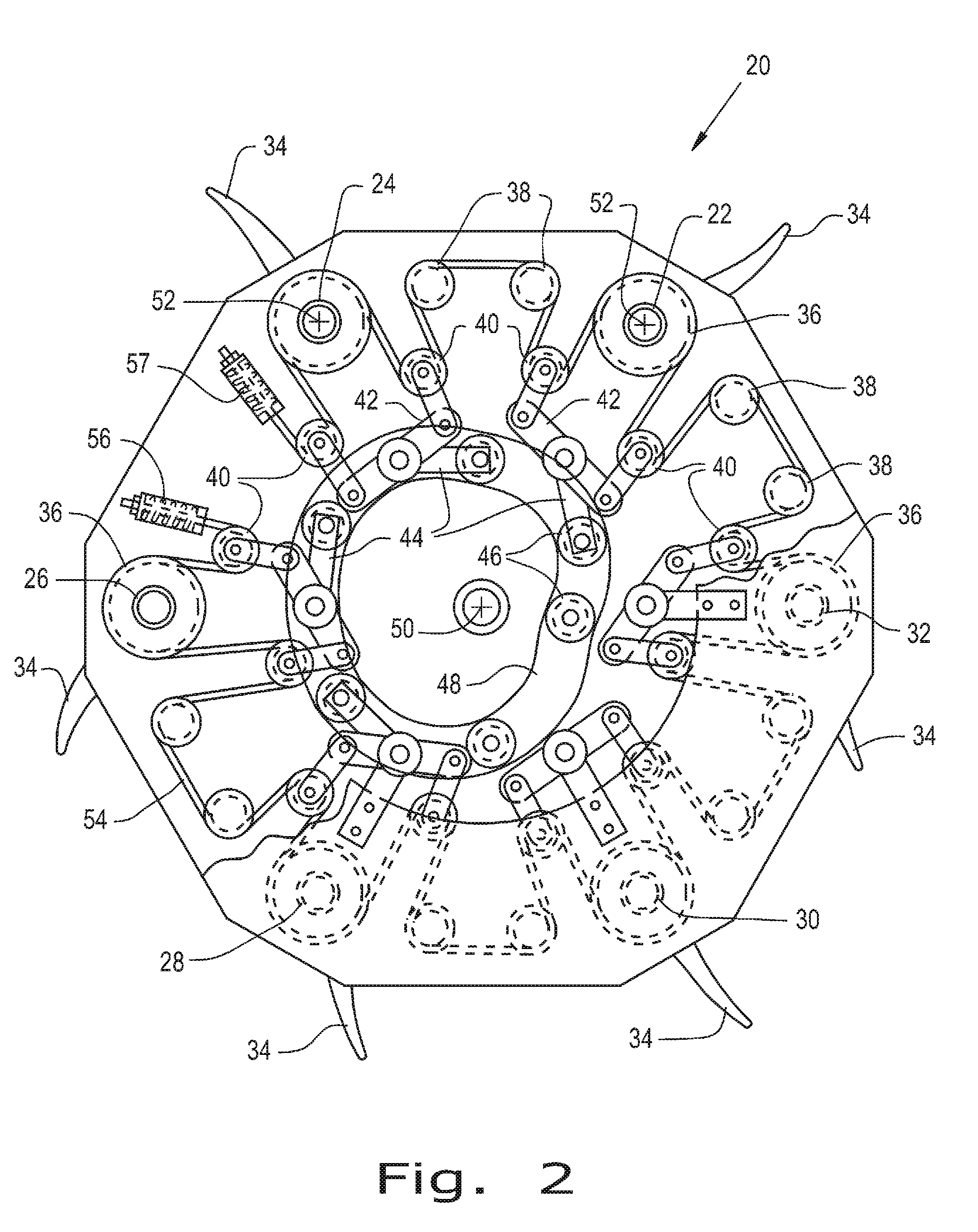
[0018]Referring now to the drawings, and more particularly to FIGS. 1-3, there is shown a harvester 10 having a header 12, a cutterbar 14, an auger 16, and a reel 18. Header 12 is pivotally connected to harvester 10, having a cutterbar 14 and a forward leading edge, which cuts the stalk of the crop and auger 16 moves the crop to a processing portion (not illustrated) within harvester 10. Reel 18 may be pivotally connected to header 12 or may be directly connected to header 12. Reel 18 extends over the top of the crop as it's being moved towards cutterbar 14 to provide for efficient cutting of the crop stalk as the crop is moved by reel 18.

[0019]Reel 18 includes a reel structural assembly 20, which may be located at either one or both ends of reel 18 and may even have a section located between the distal ends of reel 18. Reel structural assembly 20 may also be understood to be a drive mechanism that utilizes the motion of reel 18 to provide controlled positioning of bat rods 22, 24, ...


PUM


Abstract

A harvesting machine having a ground contacting propulsion system, a chassis connected to the ground propulsion system, and a header. The header has a bat reel assembly rotatingly attached to the header. The bat reel assembly includes at least one reel structural assembly, a plurality of bat rods, a tensioned member, and at least one moveable pivotal member. The at least one reel structural assembly is configured to rotate about an axis. The plurality of bat rods are pivotally connected to the at least one reel structural assembly. The plurality of bat rods include a first bat rod and a second bat rod. The tensioned member is drivingly coupled to the first bat rod and the second bat rod. The at least one pivotal member is in contact with the tensioned member. The at least one moveable pivotal member is located between the first bat rod and the second bat rod along a path of the tensioned member.

Description

CROSS REFERENCE TO RELATED APPLICATIONS[0001]This is a non-provisional application based upon U.S. provisional patent application Ser. No. 61 / 301,361, entitled “Harvester Header,” filed Feb. 4, 2010, which is incorporated herein by reference.BACKGROUND OF THE INVENTION[0002]1. Field of the Invention[0003]The present invention relates to a harvester, and, more particularly, to a bat drive system associated with a reel of a header of the harvester.[0004]2. Description of the Related Art[0005]Combines, also known as harvesters, are commonly used by farmers all over the world to harvest their crops. Various varieties of grains, kernels, and beans that range in height from a couple of inches to several feet above the ground, are cut by the header and fed into the combine. Combines, which are designed to harvest these crops, have a floating header pivotally connected to the combine in front of a feed auger. Mounted over the header is a plurality of elongated bats arranged circumferentiall...

Claims


Application Information

Patent Timeline
Patent Type & Authority Applications(United States)
IPC IPC(8): A01D57/03A01D57/00
CPCA01D57/03A01D57/00A01D57/02
Inventor GUYER, WAYNE A.
Owner GUYER WAYNE A
Learn More