High density electrical interconnect system having enhanced grounding and cross-talk reduction capability

a high-density, electrical interconnection technology, applied in the direction of coupling device connection, coupling protective earth/shielding arrangement, electric discharge lamps, etc., can solve the problem that high-speed signals that are transferred through such interconnections are susceptible to cross-talk, high density has the significant drawback of inducing cross-talk between signal contacts, undesired signals, etc., to achieve the effect of reducing or eliminating cross-talk and high density

Inactive Publication Date: 2001-01-30
WINCHESTER ELECTRONICS
View PDF12 Cites 102 Cited by
  • Summary
  • Abstract
  • Description
  • Claims
  • Application Information

AI Technical Summary

Benefits of technology

It is, therefore, an object of the present invention to provide a high density electrical interconnect system that r

Problems solved by technology

The high speed signals that are transferred through such interconnects are susceptible to cross-talk due to the signal speeds and proximate locations of the signal carrying conductors adjacent to each other.
The major drawback of such systems is that

Method used


Image

  • High density electrical interconnect system having enhanced grounding and cross-talk reduction capability
  • High density electrical interconnect system having enhanced grounding and cross-talk reduction capability
  • High density electrical interconnect system having enhanced grounding and cross-talk reduction capability

Examples


Embodiment Construction

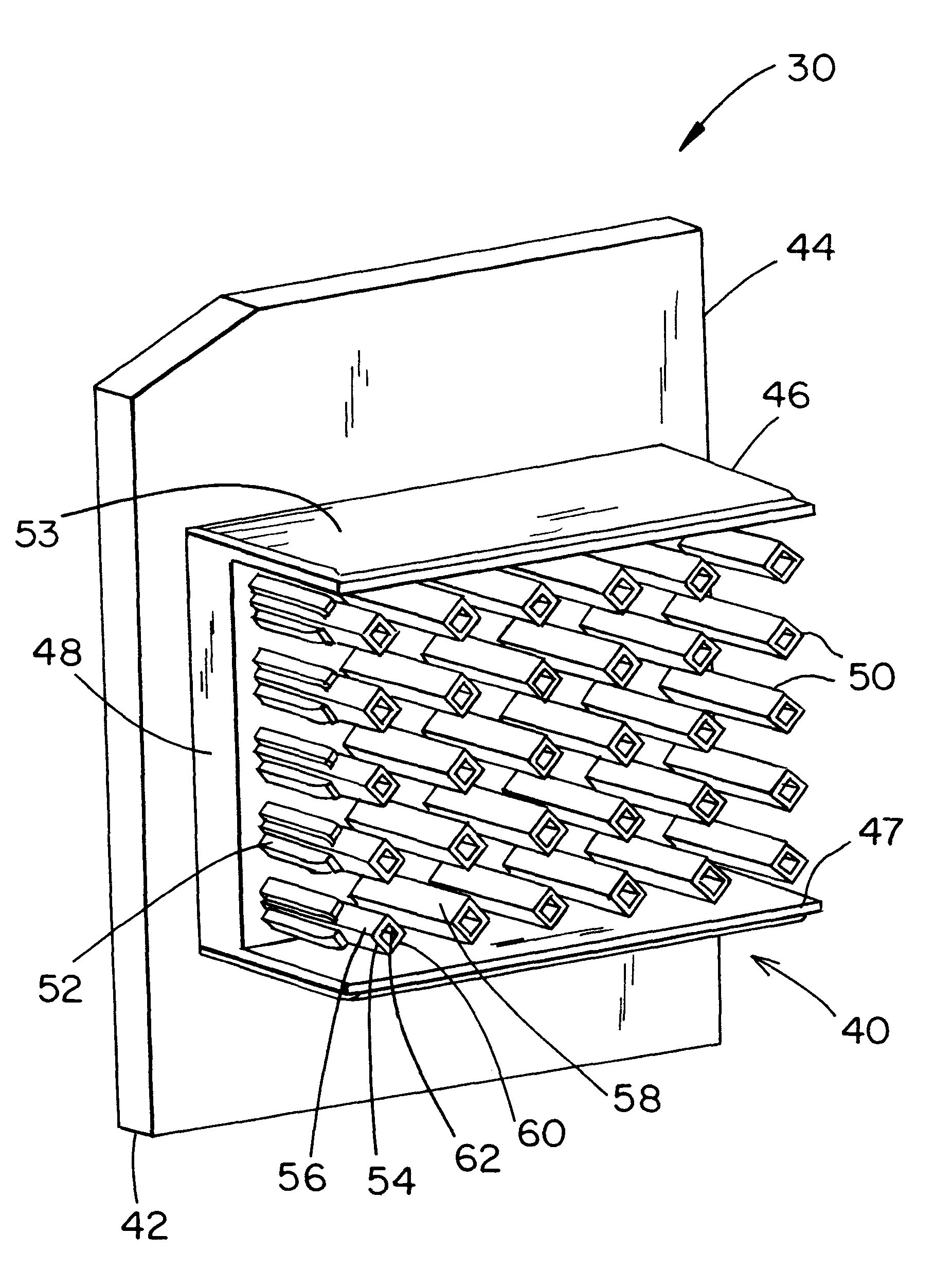
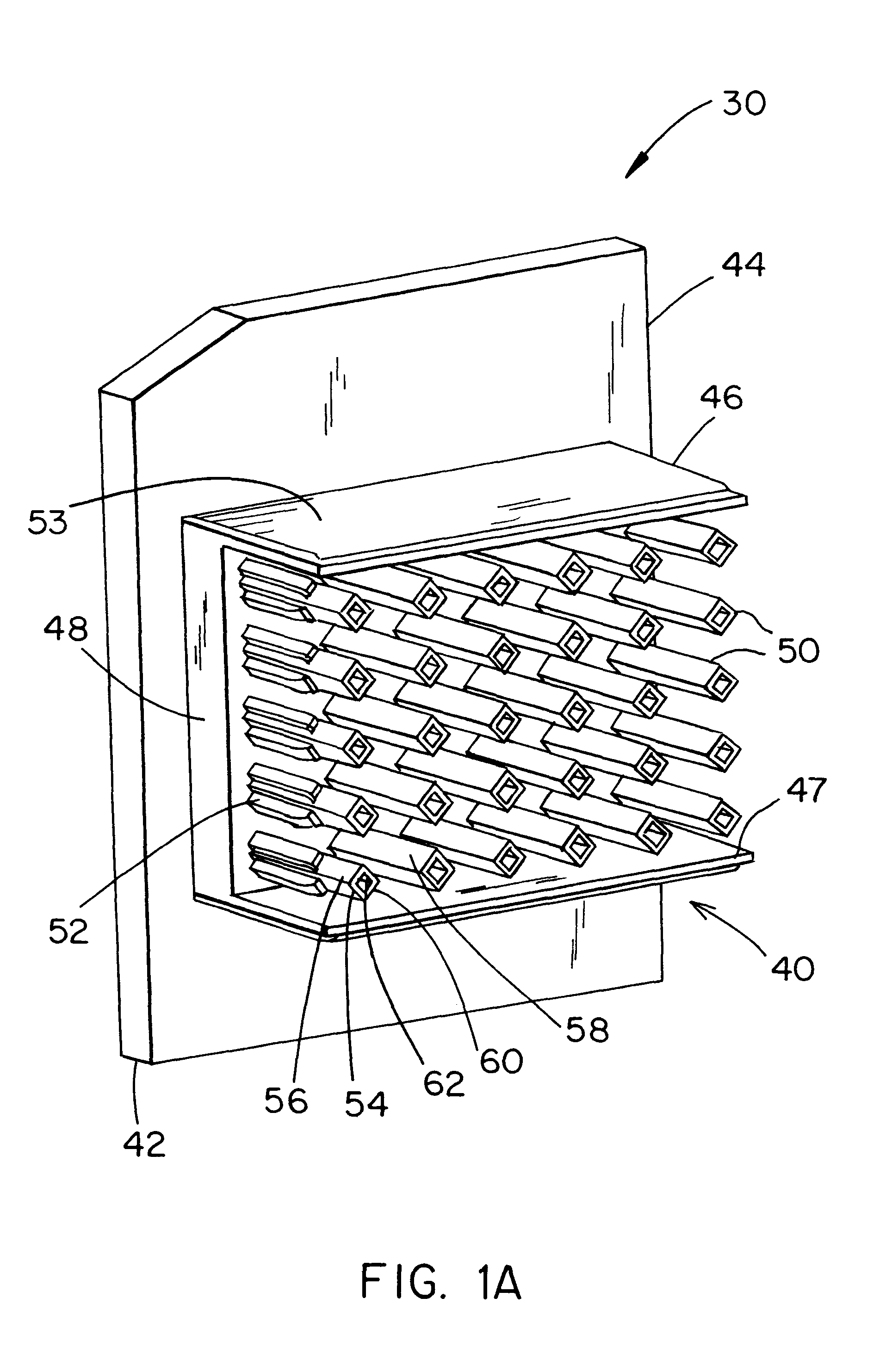
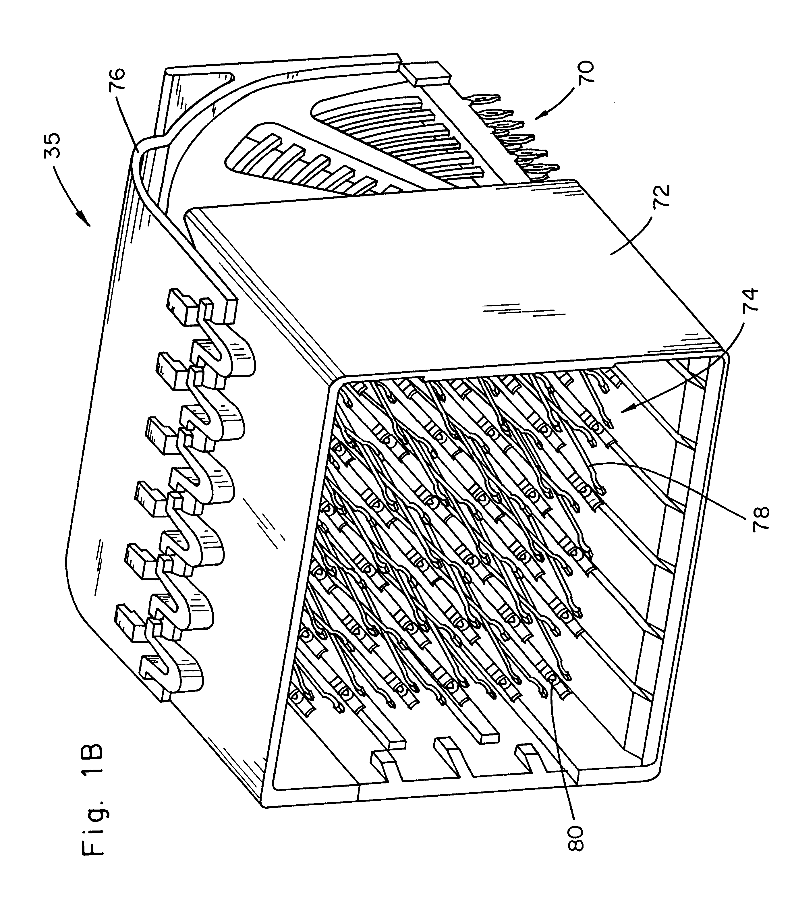
Referring first to the drawings, FIGS. 1A and 1B depict a high-density electrical interconnect system 30 including a backpanel connector 40 and a daughter card connector 35 according to the present invention. One side of the backpanel connector 40 is mounted to a backpanel 42 and one side of the daughter card connector 35 is mounted to a daughter card (not shown) so that the electrical interconnect system 30 can be used to effect electrical interconnection of a large number of electrical signals between the backpanel 42 and the daughter card when the backpanel connector 40 and a daughter card connector 35 are mated together. As can be appreciated, the principles of the present invention can be applied to devices other than daughter cards and backpanels and such are only used herein for descriptive purposes. For example, instead of right angle connection depicted in FIG. 1, the daughter card connector could be a straight connector. As depicted, the invention is described with respect...


PUM


Abstract

Disclosed is an electrical interconnect system using multiple grounding methods to reduce or prevent spurious signals from interfering with high density contacts carrying high speed transmissions. A first connector includes an insulative pillar partially surrounded by a plurality of signal contacts. A ground contact is at least partially located within the insulative pillar. A second connector includes a corresponding plurality of flexible signal contacts for mating with the signal contacts adjacent the insulative pillar. The second connector also includes a ground contact for receiving the ground contact of the first connector. The ground contacts provide a first method of providing a ground path to reduce spurious signals from entering the signal path. An electrically conducting shield is located outside the signal contacts when the first and the second connectors are mated. The first connector includes a member which provides a ground path between the first connector and the electrically conducting shield. Advantageously, the electrical interconnect system has two grounding methods which are particularly important in a high density electrical interconnect system where the contacts are closely spaced and susceptible to noise and other spurious signals.

Description

FIELD OF THE INVENTIONThe present invention relates generally to an electrical interconnection system for connecting daughter cards to an electrical backpanel, and more particularly to a high density electrical connector for connecting daughter cards to an electrical backpanel. The daughter card side of the connector and backpanel side of the interconnection system each use multiple grounding methods to ensure enhanced grounding of the respective sides of the connector to ground planes on the backpanel and daughter card, respectively. The signal carrying contacts on the daughter card and backpanel sides of the connector each have a mating grounding post to ensure reduced cross-talk between signals transmitted through adjacent contacts.BACKGROUND OF THE INVENTIONElectrical interconnect systems (including electronic interconnect systems) are used for interconnecting electrical and electronic systems and components. In general, electrical interconnect systems include both a projection-...

Claims


Application Information

Patent Timeline
IPC IPC(8): G02B6/38H01R12/00H01R13/646H01R12/16H01R12/32H01R12/26H01R13/00H01R13/46H01R13/655H01R13/658H01R13/648H01RH01R12/71H01R13/6581
CPCH01R12/71H01R13/6581H01R13/648H01R13/405H01R13/502
Inventor BRADLEY, ROBERT M.PERUGINI, MICHAEL N.
Owner WINCHESTER ELECTRONICS
Why Eureka
Try Eureka