Orthogonal connector

a connector and orthogonal technology, applied in the direction of connection contact member material, two-part coupling device, connection device connection, etc., can solve the problems of signal loss, inability to meet the requirements of the backplane, and inability to meet the requirements of the connection

Active Publication Date: 2008-02-19
TYCO ELECTRONICS LOGISTICS AG (CH)
View PDF16 Cites 100 Cited by
  • Summary
  • Abstract
  • Description
  • Claims
  • Application Information

AI Technical Summary

Problems solved by technology

Some signal loss is inherent in a trace through printed circuit board material.
The increased number of traces and the length of the traces in the backplane introduce more and more signal loss in the backplane, particularly at higher signal speeds.
Connectors oriented orthogonally may allow at least some traces to be eliminated, however, the unused length of the vias, referred to as the via stubs, at the signal connections act as filters which also cause signal loss.
Thus, the interconnection of line cards and switch cards through a backplane or midplane with minimal signal loss remains a challenge.

Method used


Image

  • Orthogonal connector
  • Orthogonal connector
  • Orthogonal connector

Examples


Embodiment Construction

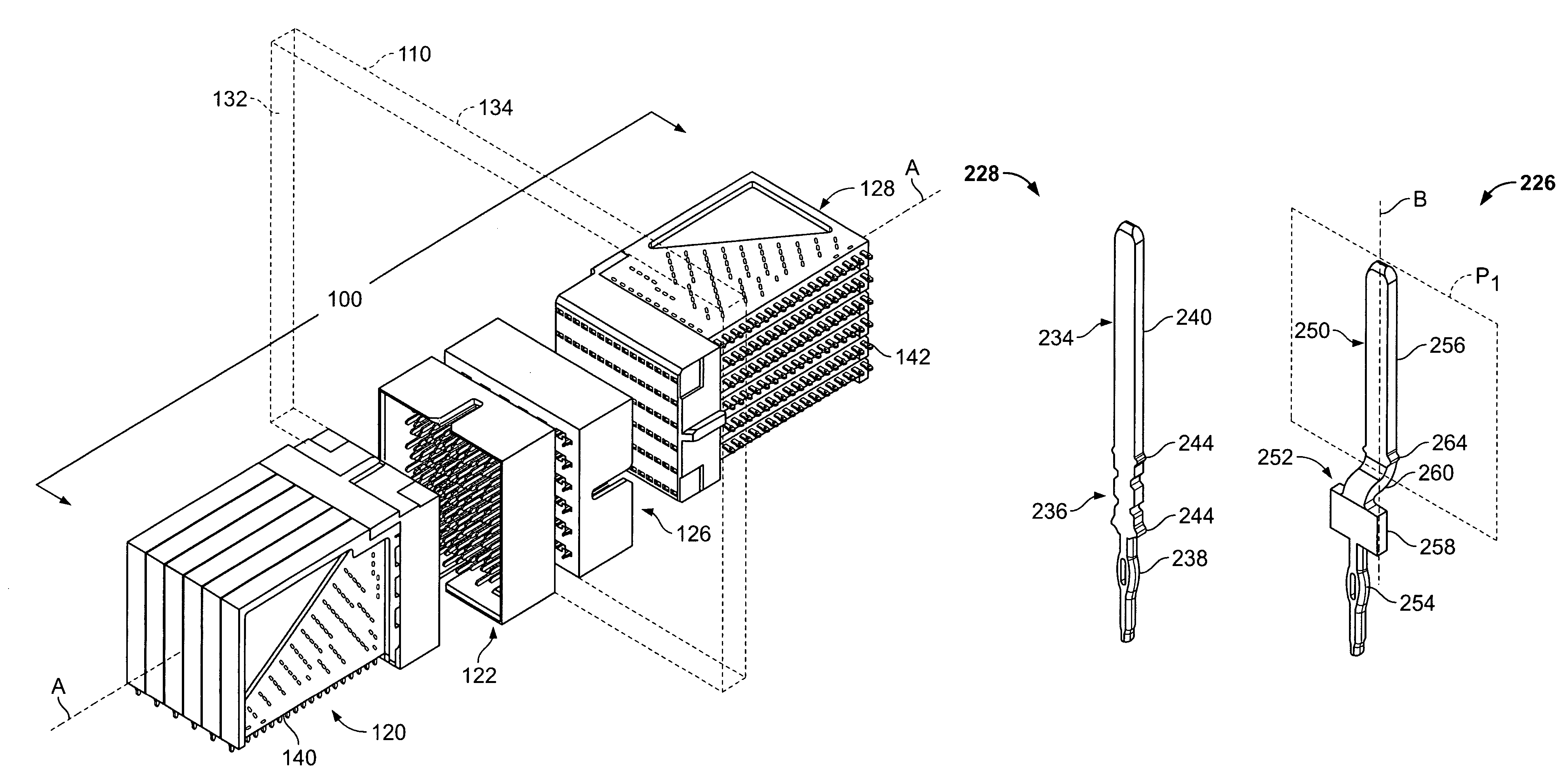
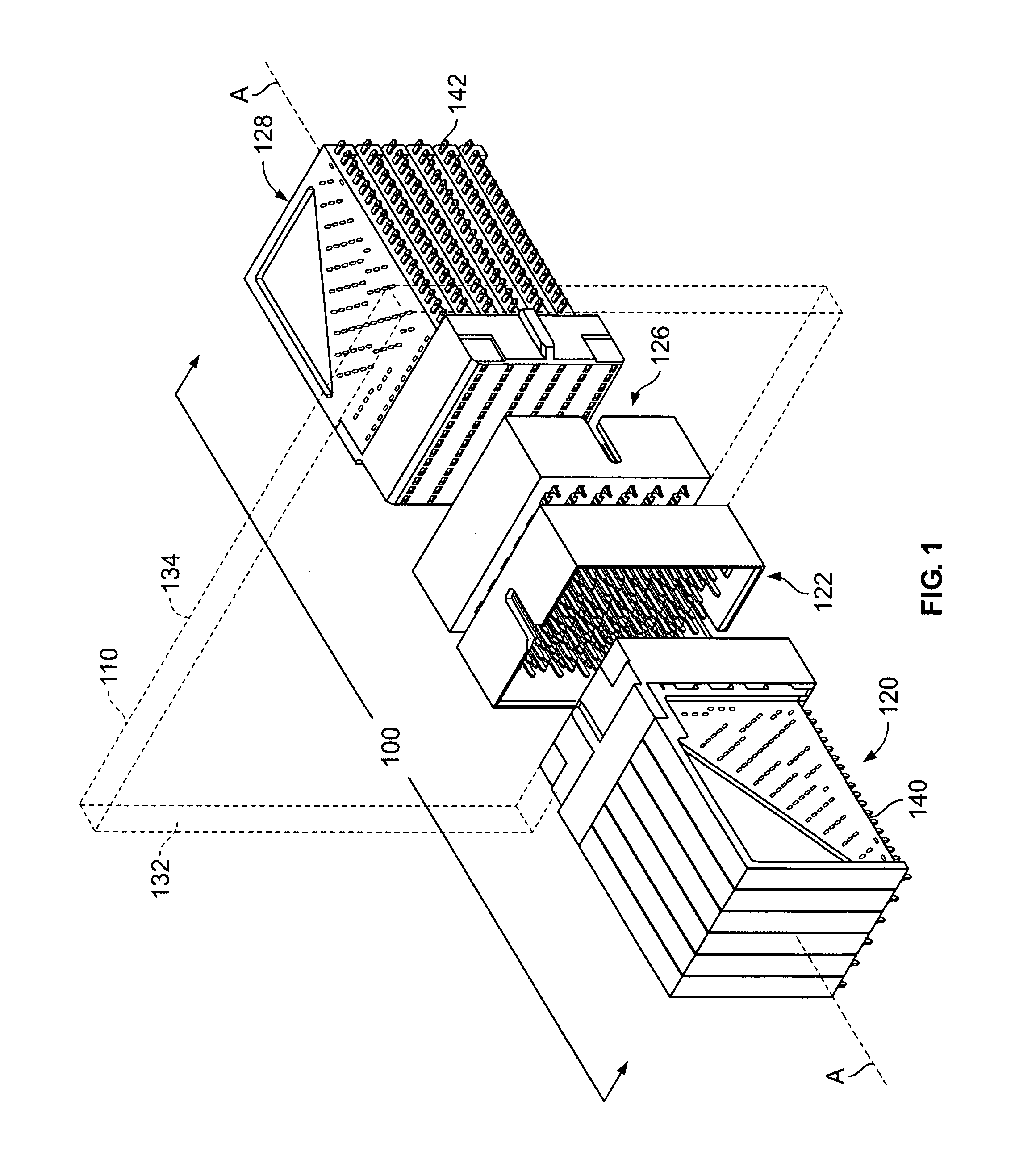
[0018]FIG. 1 is a perspective view of an orthogonal connector system 100 mounted on a midplane circuit board 110 which is shown in phantom lines for clarity. The connector system 100 includes a first receptacle connector 120, a first header connector 122, a second header connector 126, and a second receptacle connector 128. The first header and receptacle connectors 122 and 120, respectively, are mounted on a first side 132 of the midplane 110 and connect through the midplane 110 to the second header and receptacle connectors 126 and 128, respectively, which are mounted on a second side 134 of the midplane 110.

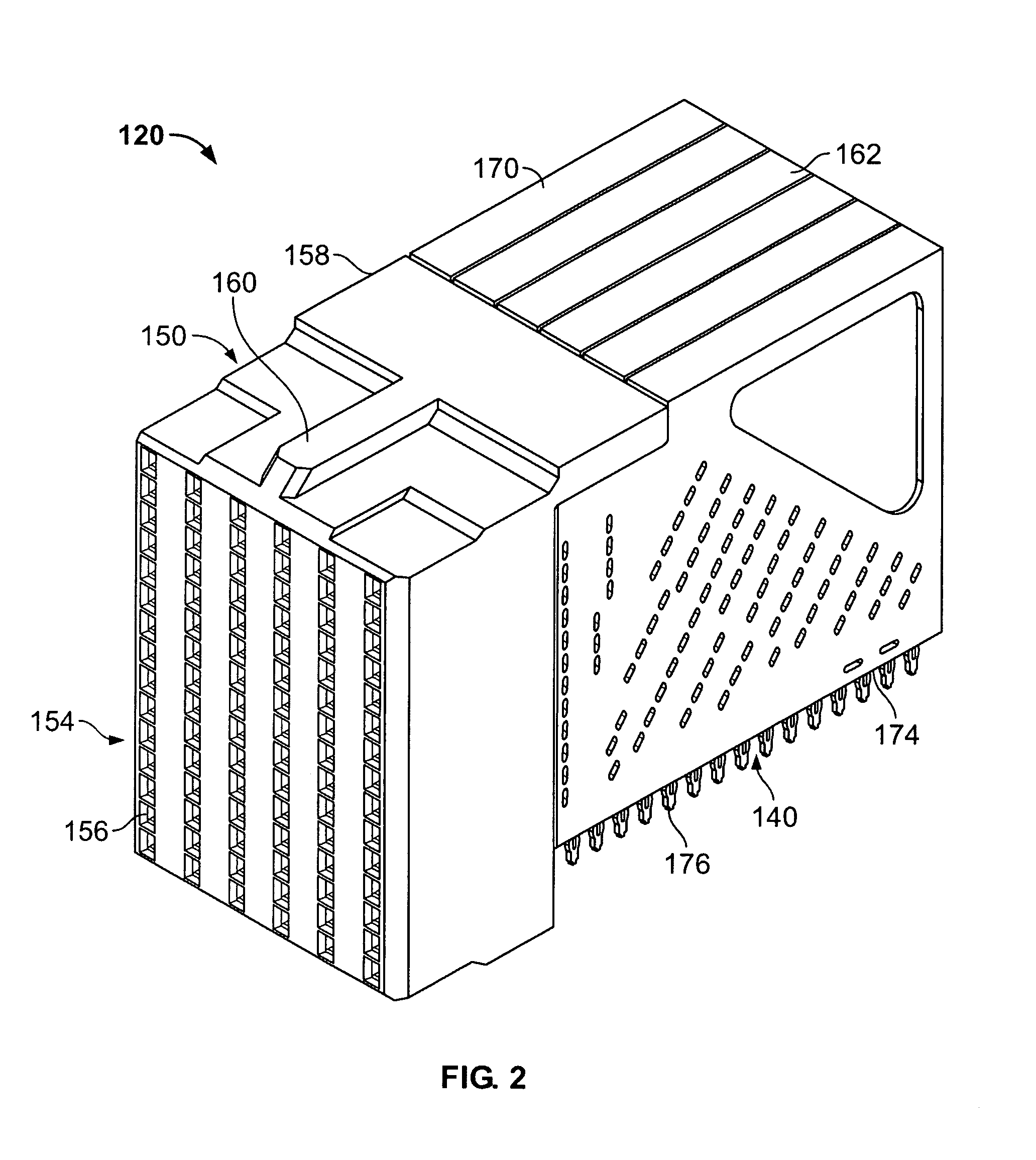
[0019]The first receptacle connector 120 includes a daughter card interface 140. By way of example only, the first receptacle 120 may be mounted on a line card (not shown) at the interface 140. Similarly, the second receptacle connector 128 includes a daughter card interface 142 and, by way of example only, the second receptacle 128 may be mounted on a switch card (not shown) ...


PUM


Abstract

An electrical connector includes a housing having a mating face and a mounting face. The housing holds signal contacts and ground contacts arranged in rows. Each of the signal contacts and ground contacts include a mating end extending from the mating face of the housing and a mounting end extending from the mounting face of the housing. For each row, the mating ends of the signal contacts and ground contacts are aligned in a common plane. The mounting ends of the ground contacts are aligned in the common plane, and the mounting ends of the signal contacts are offset from the common plane.

Description

BACKGROUND OF THE INVENTION[0001]The invention relates generally to electrical connectors and, more particularly, to a connector that may be used in an orthogonal relationship with an identical connector on both sides of a midplane.[0002]Some electrical systems, such as network switches or a computer server with switching capability, include large backplanes with several switch cards and line cards plugged into the backplane. Generally, the line cards bring data from external sources into the system. The switch cards contain circuitry that may switch data from one line card to another. Traces in the backplane interconnect the line cards and the appropriate switch cards.[0003]Some signal loss is inherent in a trace through printed circuit board material. As the number of card connections increases, more traces are required in the backplane. The increased number of traces and the length of the traces in the backplane introduce more and more signal loss in the backplane, particularly a...

Claims


Application Information

Patent Timeline
Patent Type & Authority Patents(United States)
IPC IPC(8): H01R13/648
CPCH01R12/585H01R13/514H01R23/6873H01R12/716
Inventor ROTHERMEL, BRENT RYANMORGAN, CHAD WILLIAMDAVIS, WAYNE SAMUELSHARF, ALEX MICHAELHELSTER, DAVID WAYNE
Owner TYCO ELECTRONICS LOGISTICS AG (CH)
Why Eureka
Try Eureka