Compressive contact for high speed electrical connector

a compression contact and high-speed technology, applied in the direction of electric connection bases, fixed connections, coupling device connections, etc., can solve the problems of electrical interference between adjacent signal conductors, reducing the efficiency of electrical connections, and reducing the cost of electrical connections

Active Publication Date: 2013-10-08
AMPHENOL CORP
View PDF75 Cites 107 Cited by
  • Summary
  • Abstract
  • Description
  • Claims
  • Application Information

AI Technical Summary

Problems solved by technology

Electronic systems have generally become smaller, faster and functionally more complex.
One of the difficulties in making a high density, high speed connector is that electrical conductors in the connector can be so close that there can be electrical interference between adjacent signal conductors.
Maintaining signal integrity can be a particular challenge in the mating interface of the connector.

Method used


Image

  • Compressive contact for high speed electrical connector
  • Compressive contact for high speed electrical connector
  • Compressive contact for high speed electrical connector

Examples


Embodiment Construction

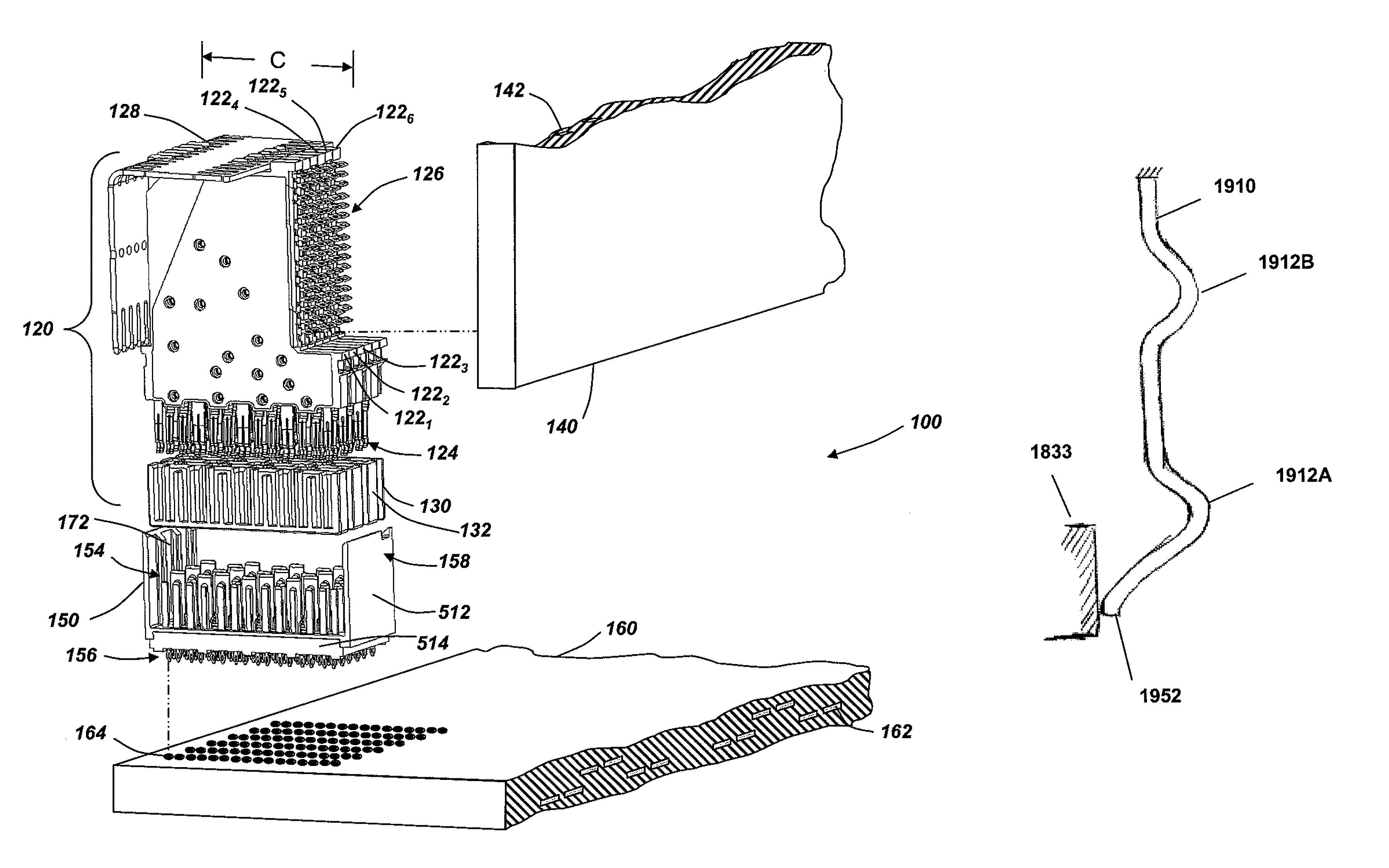
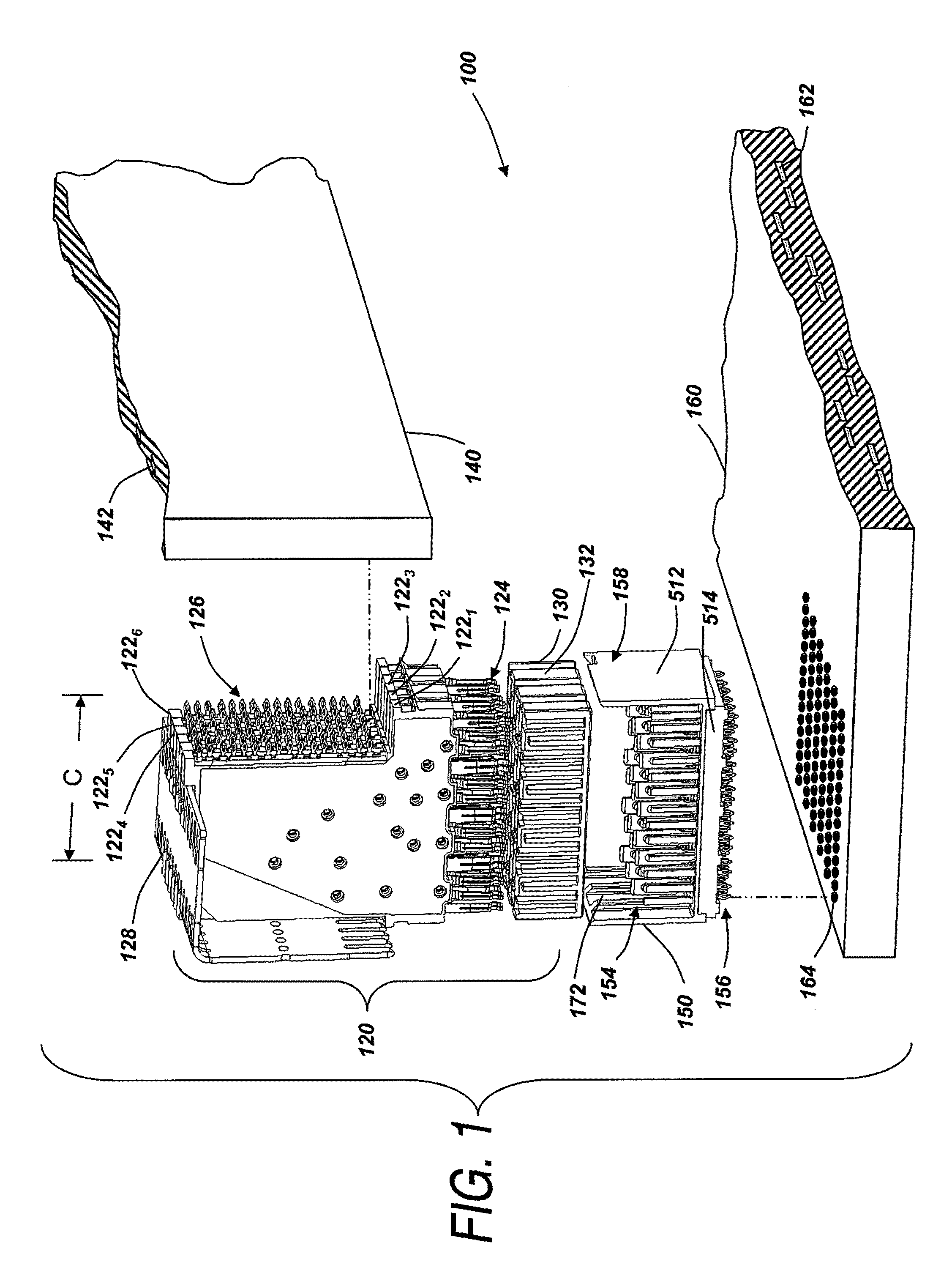
[0047]Referring to FIG. 1, an electrical interconnection system 100 with two connectors is shown. The electrical interconnection system 100 includes a daughter card connector 120 and a backplane connector 150.

[0048]Daughter card connector 120 is designed to mate with backplane connector 150, creating electronically conducting paths between backplane 160 and daughter card 140. Though not expressly shown, interconnection system 100 may interconnect multiple daughter cards having similar daughter card connectors that mate to similar backplane connections on backplane 160. Accordingly, the number and type of subassemblies connected through an interconnection system is not a limitation on the invention.

[0049]FIG. 1 illustrates an environment in which embodiments of the invention may be applied. Though FIG. 1 illustrates an interconnection system generally as is known in the art, conductive elements containing mating contact portions as described below may be substituted for some or all o...


PUM

PropertyMeasurementUnit
thicknessaaaaaaaaaa
thicknessaaaaaaaaaa
lengthaaaaaaaaaa

Abstract

An electrical interconnection system with high speed, high density electrical connectors. One of the connectors includes a mating contact portion that generates contact force as it is compressed against a wall of the connector housing. The mating contact portion has multiple segments, each with a contact region extending from the wall, such that multiple points of contact to a complementary mating contact portion in a mating connector are provided for mechanical robustness. Additionally, each signal path through the mating interface portions of the connectors can be narrow and has a relatively uniform cross section to provide a uniform impedance. Additional size reduction may be achieved by mounting a ground contact on an exterior surface of a connector housing in alternating rows. Additionally, embodiments in which a wavy contact is used in a cantilevered configuration are also described.

Description

RELATED APPLICATIONS[0001]This application claims priority under 35 U.S.C. §119(e) to U.S. Provisional Application Ser. No. 61 / 240,890, entitled “COMPRESSIVE CONTACT FOR HIGH SPEED ELECTRICAL CONNECTOR” filed on Sep. 9, 2009, which is herein to incorporated by reference in its entirety. This application claims priority under 35 U.S.C. §119(e) to U.S. Provisional Application Ser. No. 61 / 289,785, entitled “COMPRESSIVE CONTACT FOR HIGH SPEED ELECTRICAL CONNECTOR” filed on Dec. 23, 2009, which is herein incorporated by reference in its entirety.BACKGROUND OF INVENTION[0002]1. Field of Invention[0003]This invention relates generally to electrical interconnection systems and more specifically to high density, high speed electrical connectors.[0004]2. Discussion of Related Art[0005]Electrical connectors are used in many electronic systems. It is generally easier and more cost effective to manufacture a system on several printed circuit boards (“PCBs”) that are connected to one another by e...

Claims


Application Information

Patent Timeline
Patent Type & Authority Patents(United States)
IPC IPC(8): H01R11/22
CPCH01R12/58H01R13/6471H01R13/6585Y10T29/49208Y10T29/49174H01R12/00H01R13/28H01R43/00H01R12/72H01R13/658
Inventor COHEN, THOMAS S.DO, TRENT K.KIRK, BRIAN
Owner AMPHENOL CORP
Why Eureka
Try Eureka