Clamp for a plate element, especially for a photovoltaic module

a photovoltaic module and plate element technology, applied in the direction of machine supports, heat collector mountings/supports, light and heating apparatus, etc., can solve the problems of inadequate clamping properties, and achieve the effect of fast assembly

Inactive Publication Date: 2012-06-07
HILTI AG
View PDF3 Cites 55 Cited by
  • Summary
  • Abstract
  • Description
  • Claims
  • Application Information

AI Technical Summary

Benefits of technology

[0019]Moreover, it is preferred for a screw to pass through the two clamp parts and for this screw to be locked with a rail nut in order to secure the clamp to a rail, especially to a C-profile rail. According to this embodiment, when the screw is tightened, the two clamp parts can be moved from the open position into the clamping position and the clamp can be secured on the profile rail, which allows an especially fast assembly. Moreover, the spring lip can pre-tension the rail nut vis-à-vis the clamp part that is adjacent to the rail nut. This establishes a preliminary assembly position in which the clamp is temporarily held on the rail by the pre-tension ...

Problems solved by technology

There is no need for an adhesive connection, which might deteriorate wit...

Method used


Image

  • Clamp for a plate element, especially for a photovoltaic module
  • Clamp for a plate element, especially for a photovoltaic module
  • Clamp for a plate element, especially for a photovoltaic module

Examples


Embodiment Construction

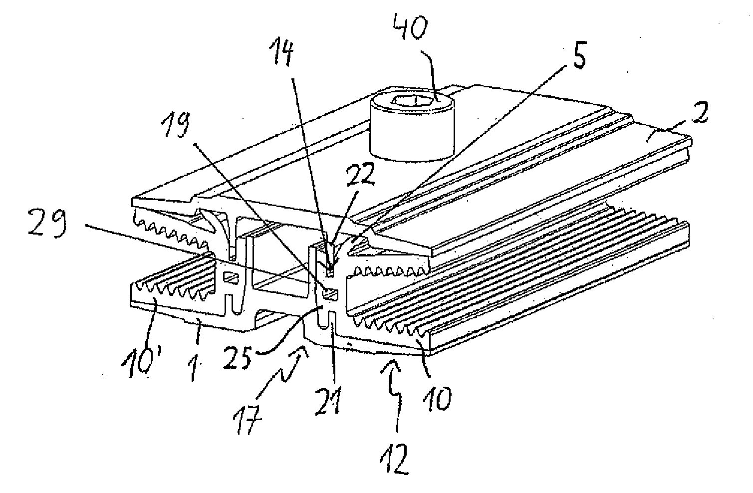
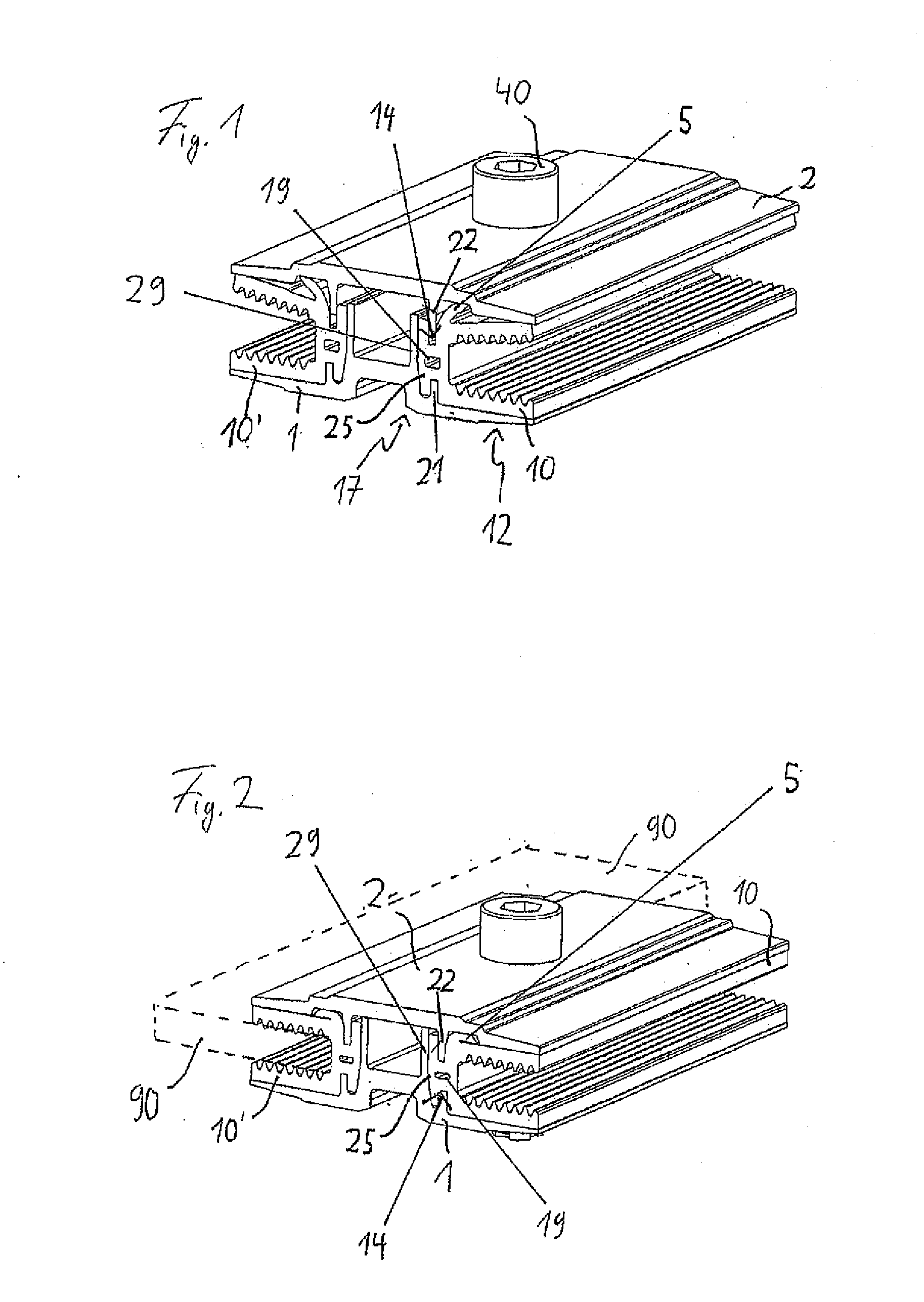
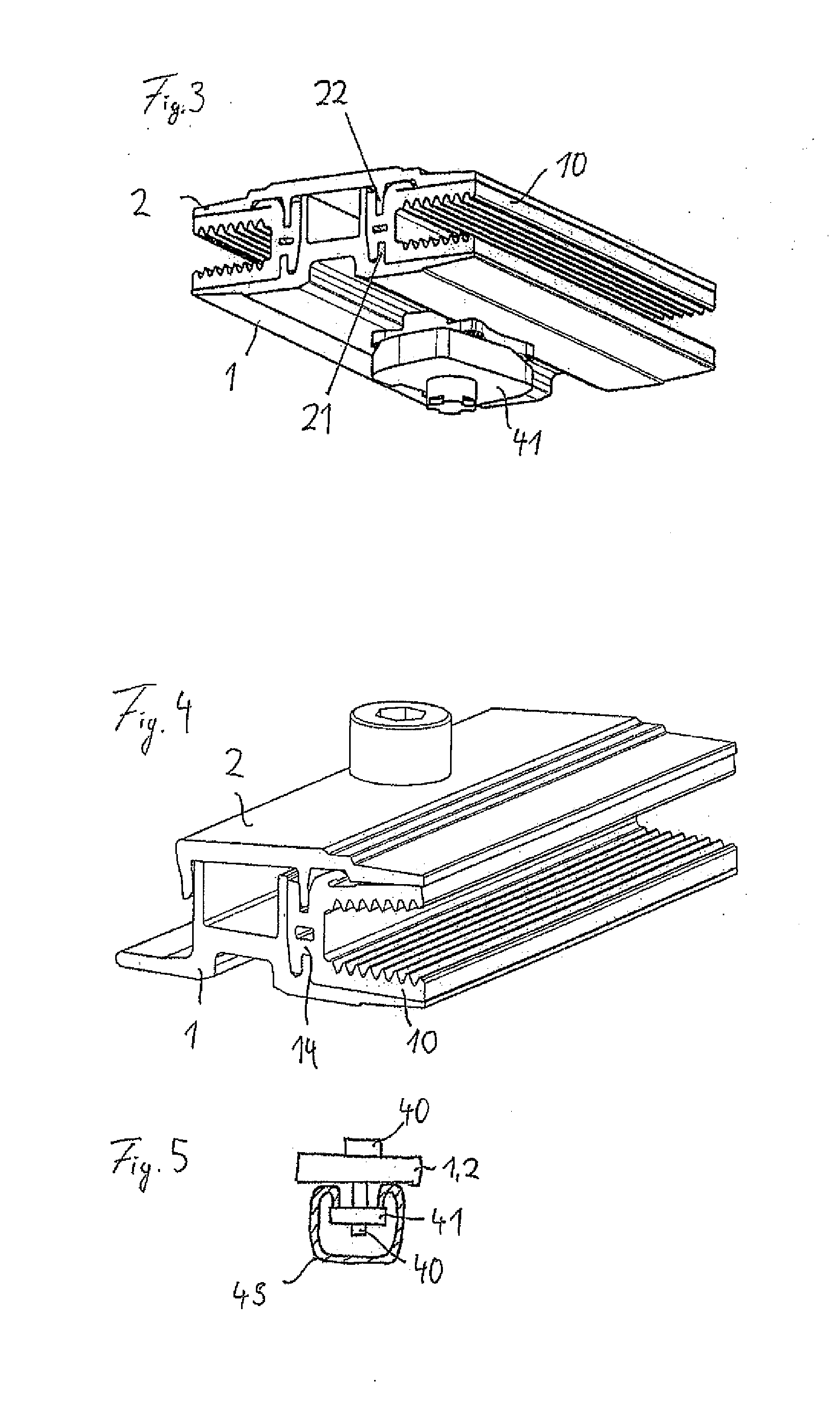
[0026]A first embodiment of a clamp according to the invention is shown in FIGS. 1 to 3. The embodiment shown in FIGS. 1 and 2 is configured as a middle clamp for affixing two plate elements and thus has two elastomer profiles 10, 10′ that each hold a plate element. For the sake of clarity, such a plate element 90 is only shown in FIG. 2, where such a plate element is depicted only in the second elastomer profile 10′.

[0027]The clamp of FIG. 1 is configured to be essentially mirror-symmetrical. Consequently, only the elastomer profile or section 10 and its arrangement shown on the right-hand side of the figure will be described in greater detail. The second elastomer profile 10′ is configured and arranged analogously.

[0028]The depicted clamp has a first clamp part 1 and a second clamp part 2, which can be moved relative to each other in the vertical direction. A screw 40 runs in the vertical direction through the two clamp parts 1 and 2, and this screw 40 serves to tighten the two cl...


PUM


Abstract

A clamp for at least one plate element, with a first clamp part and a second clamp part, the clamp parts adjustable relative to each other between an open position and a clamping position for the plate element, and with at least one elastomer profile that is arranged between the two clamp parts and that has an area with a U-shaped cross section for gripping the plate element. The elastomer profile has a clamping section that is clamped between the two clamp parts when the clamp parts are in the clamping position.

Description

[0001]This claims the benefit of German Patent Application DE 10 2010 062 384.9, filed Dec. 3, 2010 and hereby incorporated by reference herein.[0002]The invention relates to a clamp for at least one plate element, especially for at least one photovoltaic module, preferably a thin-layer photovoltaic module. A clamp of the generic type is configured with a first clamp part and a second clamp part, whereby the clamp parts can be adjusted relative to each other between an open position and a clamping position for the plate element, and with at least one elastomer profile that is arranged for placement on the plate element between the two clamp parts.BACKGROUND[0003]A clamp of the generic type for photovoltaic modules is disclosed in international patent WO 2009 / 086150 A1. Other clamps for photovoltaic modules are known from European patent application 2 090 847 A2, German utility model DE 20 2009 012 870 U1 and German utility model DE 20 2009 014 048 U1.[0004]Clamps for photovoltaic mo...

Claims


Application Information

Patent Timeline
IPC IPC(8): H01Q1/12
CPCF24J2/465F24J2/5258H02S20/00Y02E10/47Y02E10/50F24S80/70F24S25/636
Inventor KEMPLE, LORCAN
Owner HILTI AG
Why Eureka
Try Eureka