Photographic Light Output Power Control System and Method

a technology of power control system and light output, which is applied in the field of control of photographic lighting, can solve the problems of requiring significant time to change the power output of light emission, and the studio strobe typically does not have automatic power settings,

Inactive Publication Date: 2012-06-07
LAB PARTNERS ASSOC INC
View PDF0 Cites 53 Cited by
  • Summary
  • Abstract
  • Description
  • Claims
  • Application Information

AI Technical Summary

Benefits of technology

[0004]In one implementation, a method of controlling a power output level of a photographic lighting device with a photographic exposure compensation control of a camera, the photographic lighting device being set to a first power output level and the photographic exposure compensation control being set to a first compensation value is provided. The method includes changing the photographic exposure compensation control to a second compensation value; using the second compensation value and a mapping of the dynamic range of a photographic exposure compensation control of a camera to the dynamic range of a power output level of a photographic lighting device, determining a second power output level that corresponds to the second compensation value; and automatically setting the photographic lighting device to the second power output level.
[0005]In another implementation, a method of controlling a power output level of a photographic lighting device is provided. The method includes generating a mapping of the dynamic range of a photographic exposure compensation control of a camera to the dynamic range of a power output level of a photographic lighting device; providing, after said mapping, the lighting device with the power output level set to a first power output level; providing, after said mapping, the camera with the photographic exposure compensation control set to a first compensation value; changing the photographic exposure compensation control to a second compensation value; using the mapping and the second compensation value, determining a second power output level that corresponds to the second compensation value; and setting the photographic lighting device to the second power output level.
[0006]In yet another implementation, a wireless photographic communication device for synchronizing a camera to a photographic lighting device is provided. The wireless photographic communication device includes a connection to an external connector of the camera that provides a signal including a value for a current photographic exposure compensation value of the camera; a memory including information having a mapping of the dynamic range of a photographic exposure compensation control of the camera to a dynamic range of a power output level of the photographic lighting device; a transmitter; and a processor for correlating the current photographic exposure compensation value to a power output level of the lighting device and using the transmitter to wirelessly communicate the p

Problems solved by technology

Studio strobes typically do not have automated power settings that utilize automatic feedback mechanisms to set the power output.
C

Method used


Image

  • Photographic Light Output Power Control System and Method
  • Photographic Light Output Power Control System and Method
  • Photographic Light Output Power Control System and Method

Examples


Embodiment Construction

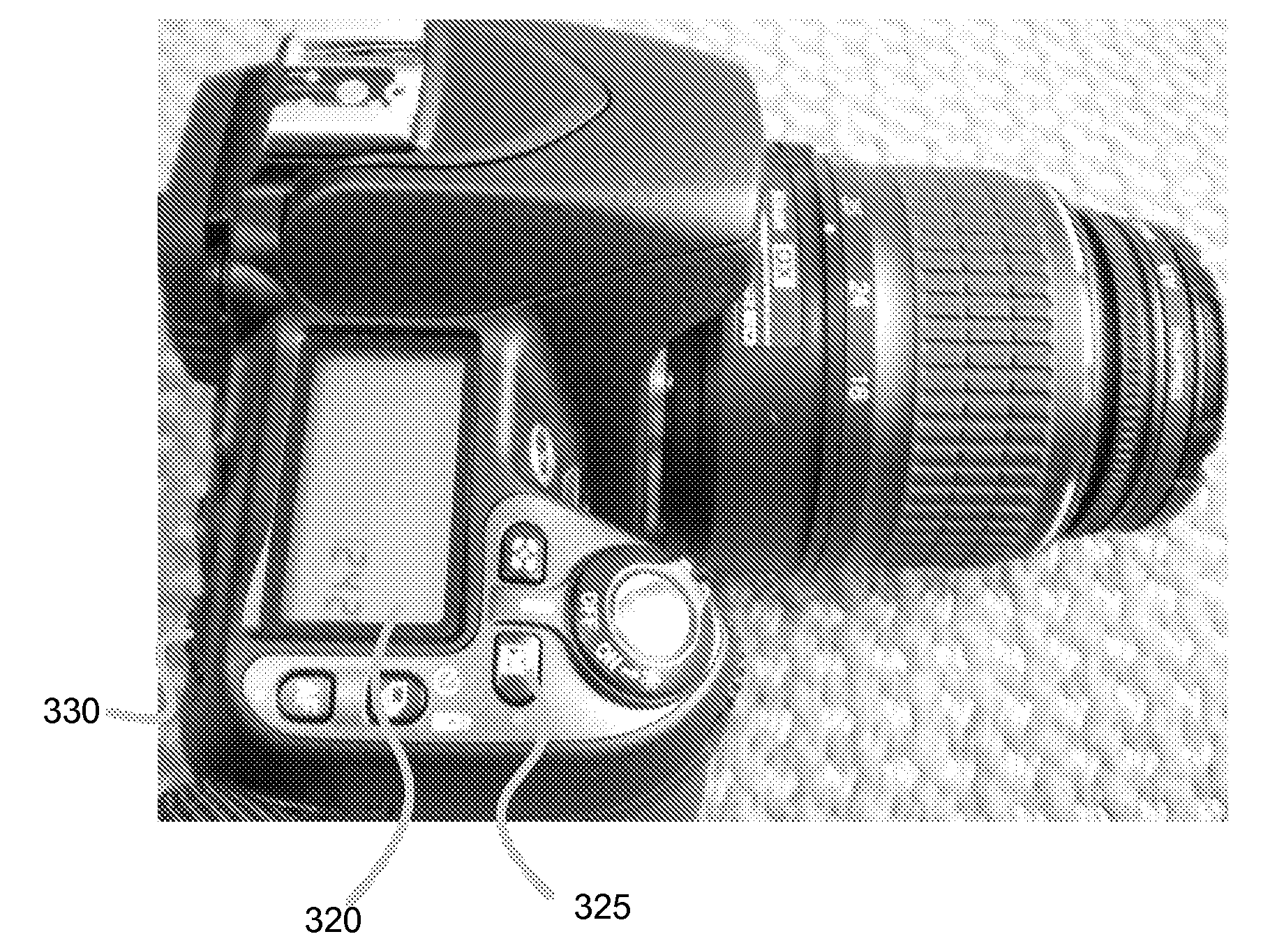
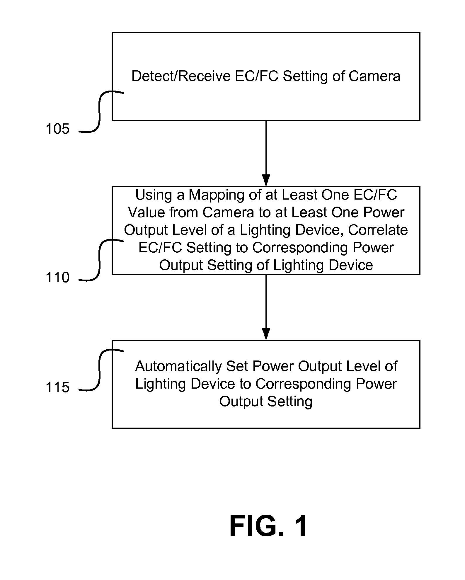
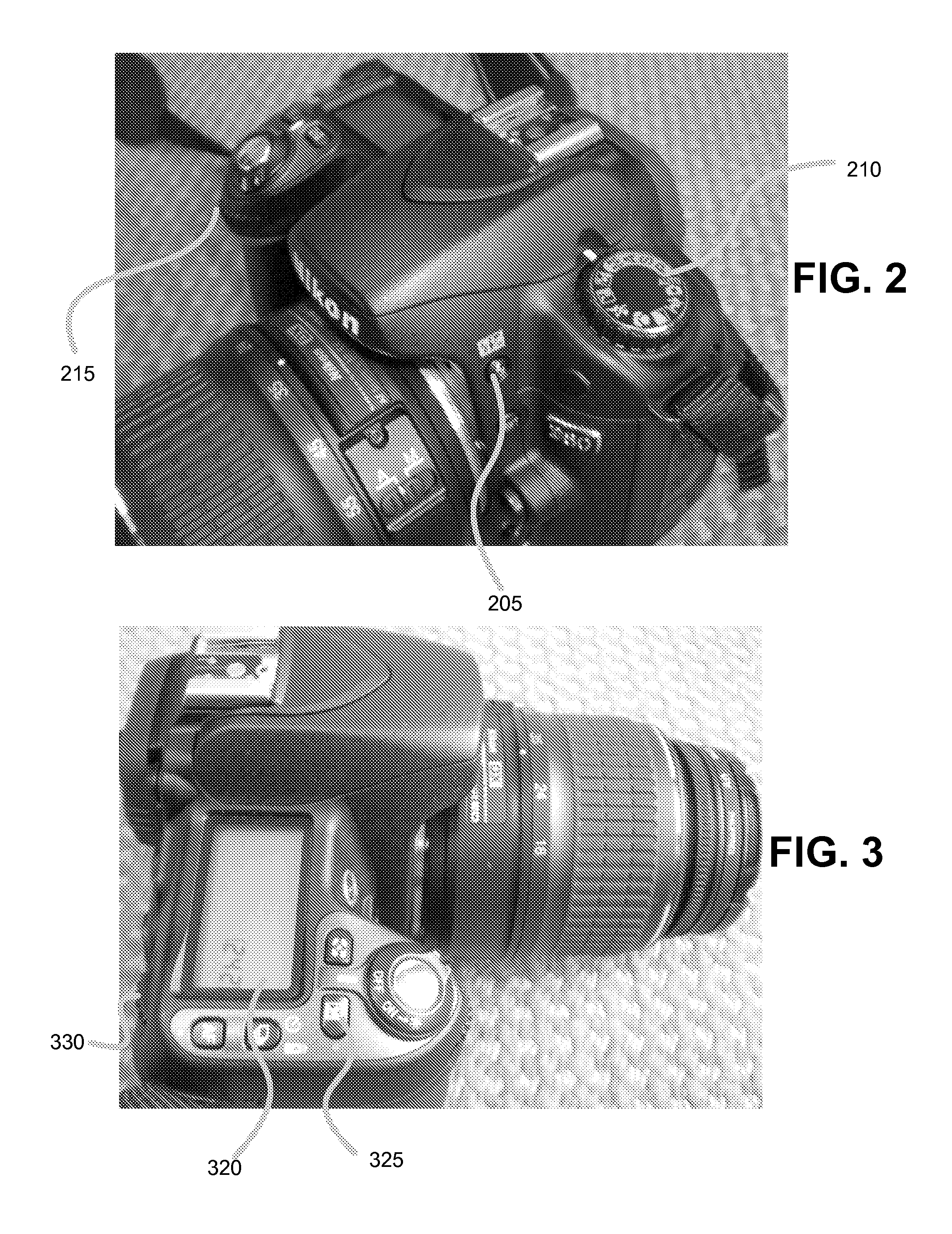
[0011]A system and method is provided for direct manual power output control of lighting devices by repurposing photographic exposure compensation controls of a camera body from the original purpose for the controls of providing an offset value to the camera body's automated exposure power value.

[0012]In one embodiment, one or more photographic exposure controls of a camera are retasked to give direct manual control of the power output level of a lighting device by mapping the dynamic range of a photographic exposure compensation control of the camera to a dynamic range of a power output level of the lighting device. In another embodiment, the mapping allows for automatically tracking changes in ISO and / or aperture of the camera to a power output level of a lighting device. In one example, automatic tracking of power control can be provided to lighting devices (such as studio strobes) that do not usually have access to automated power control from a camera.

[0013]There are two differ...


PUM


Abstract

Retasking of one or more photographic exposure controls of a camera to give direct manual control of a power output level of a lighting device by mapping a dynamic range of a photographic exposure compensation control of the camera to a dynamic range of a power output level of the lighting device. In another example, mapping is used in automatic tracking of changes in ISO and/or aperture of a camera to a power output level of a lighting device. In one example, automatic tracking of power control can be provided to lighting devices (such as studio strobes) that do not usually have access to automated power control from a camera.

Description

RELATED APPLICATION DATA[0001]This application claims the benefit of priority of U.S. Provisional Patent Application Ser. No. 61 / 152,245, filed Feb. 12, 2009, and titled “Photographic Light Output Power Control System and Method”, which is incorporated by reference herein in its entirety.FIELD OF THE INVENTION[0002]The present invention generally relates to the field of control of photographic lighting. In particular, the present invention is directed to a photographic light output power control system and method.BACKGROUND[0003]Photographic lighting devices typically come in a variety of sizes and capabilities for different functions, from those for the amateur hobbiest to the full-time professional applications. Two popular categories of lighting devices include speedlights and studio strobes. Speedlights are usually smaller in size and power output than studio strobes. However, modern speedlights often are configured with, and / or utilize, automated capabilities such as photograph...

Claims


Application Information

Patent Timeline
IPC IPC(8): H04N5/232H04N5/235
CPCG03B15/05H04N5/2354H04N5/235G03B2215/05H04N23/70H04N23/74
Inventor CLARK, JAMES E.
Owner LAB PARTNERS ASSOC INC
Why Eureka
Try Eureka