Surgical instrument and operation support system having the surgical instrument

a technology of surgical instruments and support systems, applied in the field of surgical instruments and operation support systems, can solve problems such as the deterioration of surgical instruments

Inactive Publication Date: 2012-06-07
OLYMPUS CORP
View PDF7 Cites 261 Cited by
  • Summary
  • Abstract
  • Description
  • Claims
  • Application Information

AI Technical Summary

Problems solved by technology

However, such a surgical instrument deteriorates after used more than once, and the deterioration can cause trouble during use.

Method used


Image

  • Surgical instrument and operation support system having the surgical instrument
  • Surgical instrument and operation support system having the surgical instrument
  • Surgical instrument and operation support system having the surgical instrument

Examples


first embodiment

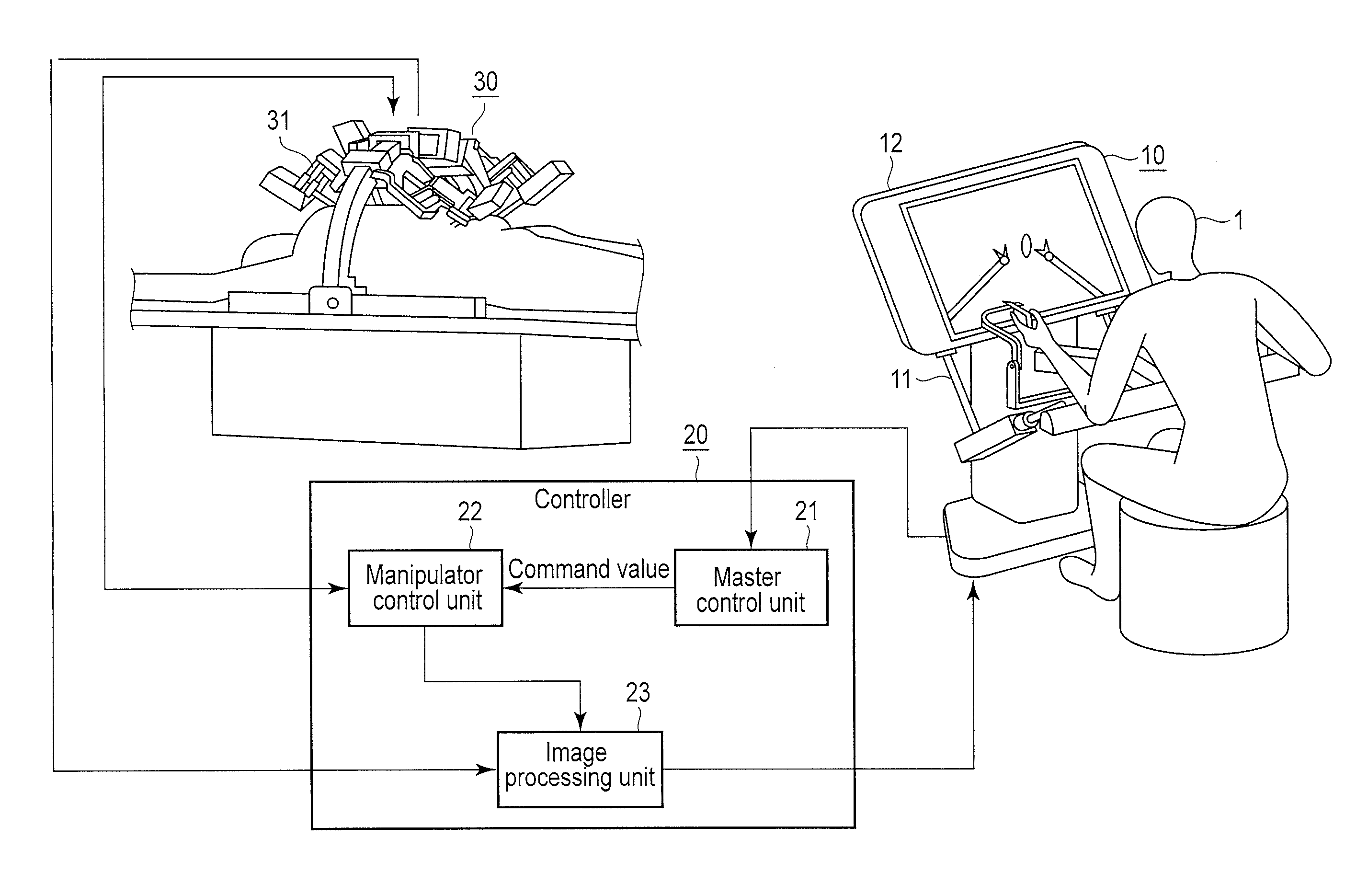
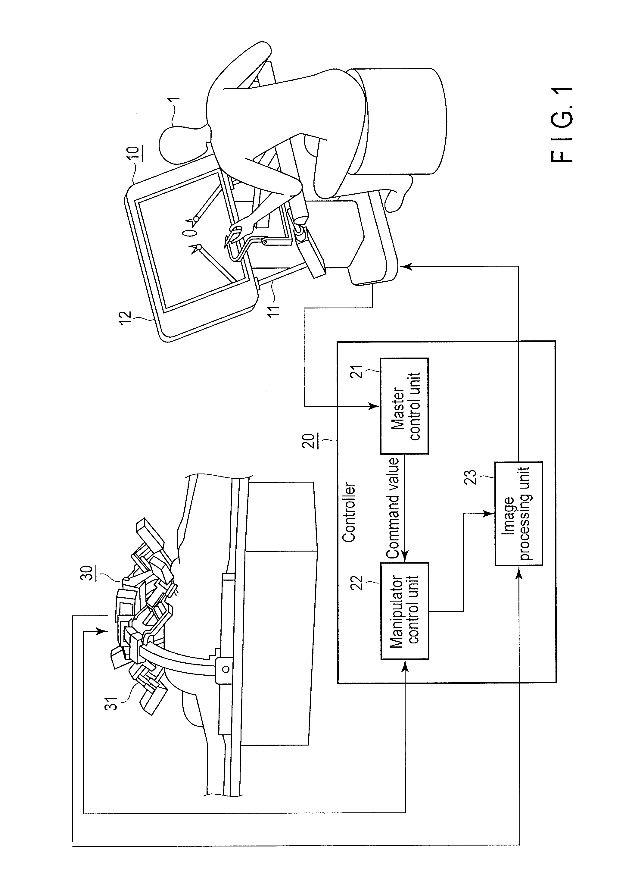
[0024]FIG. 1 is a diagram showing the overall configuration of a master-slave manipulator as an example of an operation support system according to embodiments of the present invention. As shown in FIG. 1, the master-slave manipulator according to the present embodiments comprises a remote operation device 10, a controller 20, and a slave manipulator 30.

[0025]The remote operation device 10 functions as a master in the present master-slave manipulator, and comprises an operation unit 11 and a display unit 12.

[0026]The operation unit 11 comprises, for example, driving shafts and a gripper. An operator 1 operates the operation unit 11 so that the driving shafts constituting the operation unit 11 are driven. The driving amount of each driving shaft is detected by an unshown position sensor (e.g., an encoder) provided in each driving shaft. A detection signal of each position sensor is output to the controller 20 as a signal (operation signal) that indicates operation information for the...

second embodiment

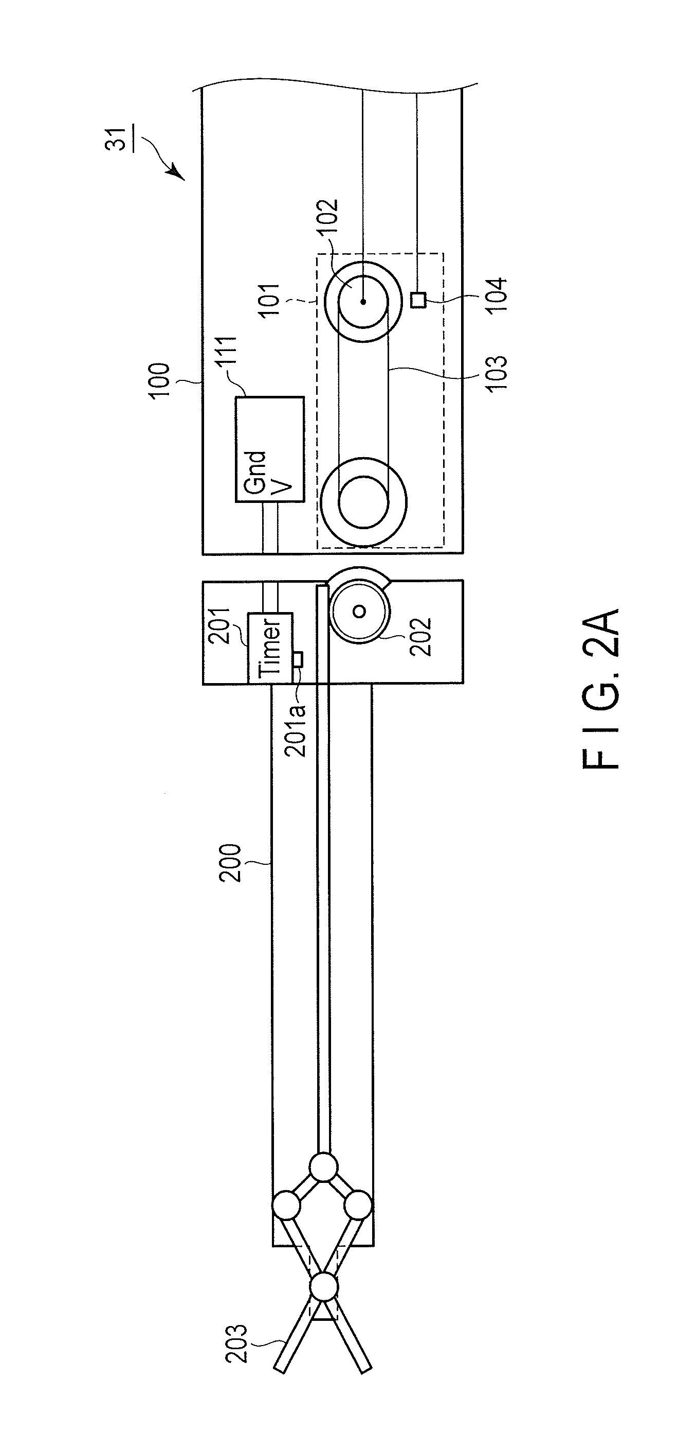
[0053]Now, the second embodiment of the present invention is described. In the first embodiment described above, the time in which the surgical instrument distal end 200 is attached to the positioning arm 100 is measured as the life of the surgical instrument distal end 200. In contrast, in the example according to the second embodiment, the number of times or the time in which the surgical instrument distal end 200 is actually used (operated) is measured as the life of the surgical instrument distal end 200.

[0054]FIG. 6 is a diagram showing the configuration of a slave arm 31 according to the second embodiment of the present invention. The slave arm 31 shown in FIG. 6 also comprises a positioning arm 100 and a surgical instrument distal end 200. Components similar to those in FIG. 2A are provided with the same reference signs similar to those in FIG. 2A and are not described below.

[0055]An electricity supply unit 111 in FIG. 6 is conductively connected to a counter IC 201 in the su...


PUM


Abstract

A surgical instrument includes a use measurement unit. The use measurement unit acquires a use time or an operation amount of the surgical instrument in response to the use or operation of the surgical instrument. The use measurement unit acquires motion of a gripper or a joint provided in the surgical instrument as the use time or the operation amount.

Description

CROSS-REFERENCE TO RELATED APPLICATIONS[0001]This application is based upon and claims the benefit of priority from the prior Japanese Patent Application No. 2010-269301, filed Dec. 2, 2010, the entire contents of which are incorporated herein by reference.BACKGROUND OF THE INVENTION[0002]1. Field of the Invention[0003]The present invention relates to a surgical instrument and an operation support system having such a surgical instrument.[0004]2. Description of the Related Art[0005]Recently, in order to reduce manpower in medical facilities, medical procedures using robots have been under study. Particularly in the field of surgery, various suggestions have been made regarding medical manipulator systems (operation support systems) that use a multidegree-of-freedom manipulator having a multidegree-of-freedom arm to treat a patient. In such a medical manipulator system, various surgical instruments such as a gripper and forceps are attached to the end of the arm. These surgical instr...

Claims


Application Information

Patent Timeline
Patent Type & Authority Applications(United States)
IPC IPC(8): A61B19/00
CPCA61B19/2203A61B2019/4815A61B2019/2223A61B34/30A61B34/37A61B2090/0803
Inventor KISHI, KOSUKE
Owner OLYMPUS CORP
Why Eureka
Try Eureka