Control device, charge storage system, control method, and computer program

Active Publication Date: 2012-06-14
PANASONIC CORP
View PDF2 Cites 12 Cited by
  • Summary
  • Abstract
  • Description
  • Claims
  • Application Information

AI Technical Summary

Benefits of technology

[0015]According to the electric power storage system according to the present invention, a depth of charge and discharge is determined while the life properties of the battery and the difference in the dynamic price of electricity are considered. Thereby, economic merits of the electric power storage system can be maximized.
[0016]This ca

Problems solved by technology

This is because the storage battery

Method used


Image

  • Control device, charge storage system, control method, and computer program
  • Control device, charge storage system, control method, and computer program
  • Control device, charge storage system, control method, and computer program

Examples


Example

Embodiment 1

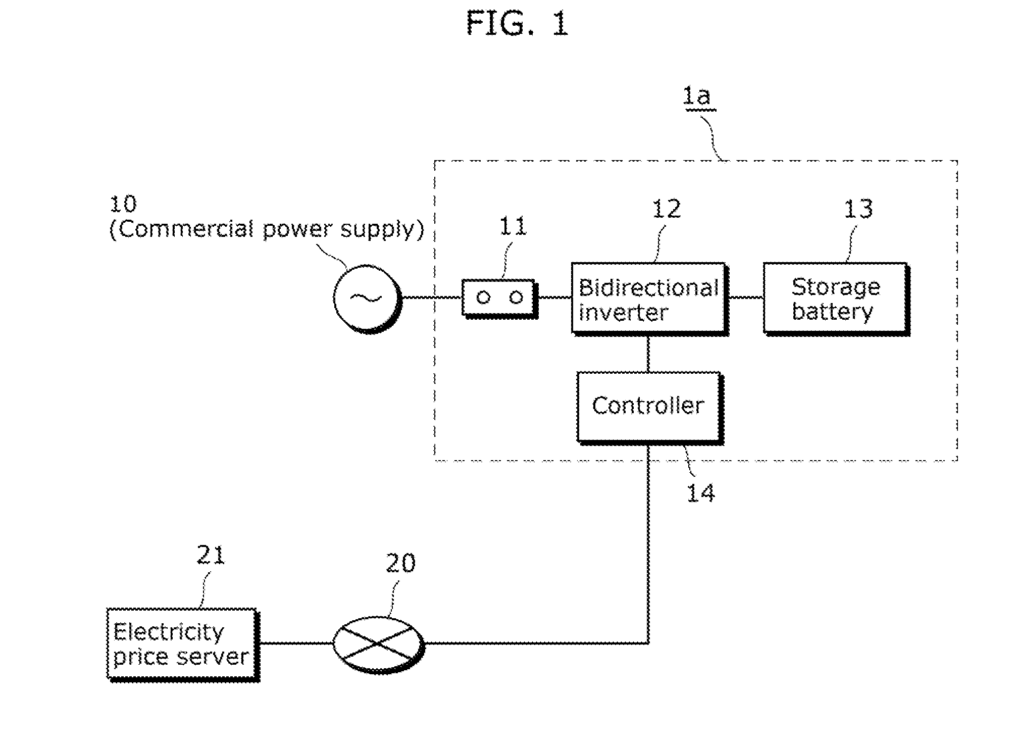
[0036]FIG. 1 is a block diagram of an electric power storage system 1a according to Embodiment 1.

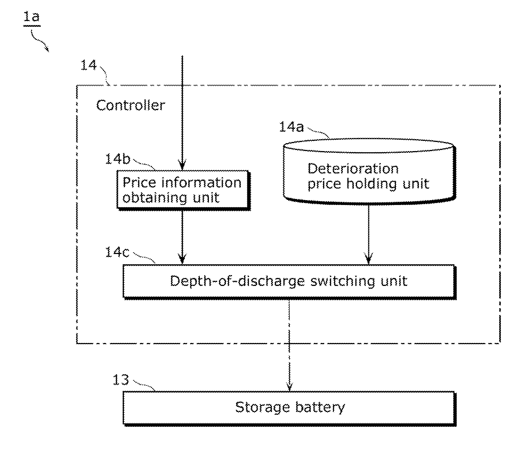
[0037]The electric power storage system 1a includes a connection unit 11, a bidirectional inverter 12, a storage battery 13, and a controller 14.

[0038]The connection unit 11 is a connection terminal to the commercial power system 10, and accommodates a circuit breaker for protecting the commercial power system 10 and the bidirectional inverter 12 from an accident.

[0039]The bidirectional inverter 12 is connected to the commercial power system 10 via the connection unit 11, and bidirectionally converts the alternating current of the commercial power system 10 and the direct current of the storage battery 13. The direction and amount of electric power to be converted by the bidirectional inverter 12, i.e., the direction and amount of the storage battery 13 to be charged and discharged is instructed by the controller 14.

[0040]The storage battery 13 temporarily stores the electric...

Example

Embodiment 2

[0062]In the electric power storage system 1a in FIG. 1, examine the case where the relationship between the depth of discharge x of the storage battery 13 (0≦x≦1) and the cycle life N is given by a function N(x). In this case, if the current time is t=0 and a next cost function TC(·) is minimized, the amount of electric power to be charged and discharged of the storage battery 13Δst at each time t (=0, 1, . . . T−1) can be determined.

[Math.1]TC(Δs0,Δs1,…,ΔsT-1)=∑t=0T-1{PC(Δst,t)+PC·N(1-st / C)-N(1-st+1 / C)N(1-st / C)N(1-st+1 / C)·u(-Δst)}(1)

[0063]Here, a function PC(Δst, t) of the first term within the curly brackets in (1) designates the electricity price produced within a time step at the time t wherein the amount of electric power to be charged and discharged of the storage battery 13 at the time t is Δst. Here, if the price of electricity (unit price) at the time t obtained from the electricity price server 21 is expressed with R(t), the function PC(Δst, t) can be calculat...

Example

Embodiment 3

[0085]FIG. 5 is a block diagram of an electric power storage system is according to Embodiment 3.

[0086]In FIG. 5, same reference numerals will be given to same components as those in FIG. 1, and the description thereof will be properly omitted.

[0087]As shown in FIG. 5, in the case where the electric power storage system is installed with an electric power consuming apparatus 51 in a location of a user, if the electric power consuming apparatus 51 has a small demand for electric power, discharge by the electric power storage system may cause reverse power flow (selling) to the commercial power system 10. In this case, a wattmeter 52 is installed, and the controller 14 determines the amount of electric power to be charged and discharged Δst such that the reverse power flow is not produced. Alternatively, considering the selling price at the time of the reverse power flow, the controller 14 may calculate the function PC(Δst, t). In order to perform these, usually, predictio...


PUM


Abstract

In an electric power storage system connected to a commercial power system, a controller (14) includes a deterioration price holding unit (14a) that holds discharge costs in association with depths of discharge of a storage battery (13), a price information obtaining unit (14b) that obtains a price of electricity, and a depth-of-discharge switching unit (14c) that discharges the storage battery at a depth of discharge at which the discharge cost held in association with the depth of discharge does not exceed a difference in the price, so as to properly determine the depth of charge and discharge in consideration of life properties of the battery and the difference in the price in the dynamically changing price of electricity.

Description

TECHNICAL FIELD[0001]The present invention relates to an electric power storage system for commercial power.BACKGROUND ART[0002]Use of storage batteries for storage of commercial power has been examined along with progress of the battery techniques accompanied by widespread use of notebook computers and portable information apparatuses in these days. For example, Patent Document 1 discloses a configuration of an electric power storage system for commercial power using a battery module in which a plurality of compact storage batteries are connected in parallel and in series.[0003]Recently, as application of these electric power storage systems for commercial power, smoothing of electric power generated by wind power generation and solar power generation has received attention. Moreover, it has been examined that the electric power is charged during the night when an electricity price is low, and discharged during the daytime when the electricity price is high, thereby to reduce an el...

Claims


Application Information

Patent Timeline
IPC IPC(8): G06Q50/06G06Q40/00
CPCH02J7/042G06Q40/00H02J7/007H02J7/04
Inventor KAJI, MITSURU
Owner PANASONIC CORP
Why Eureka
Try Eureka