
Clutch retainer sealed to cover

a technology of retainer and clutch, which is applied in the direction of fluid gearing, coupling, belt/chain/gearing, etc., can solve the problems of degrading the operation of the torque converter, poor clutch performance, and difficult to remov

Inactive Publication Date: 2012-06-21
SCHAEFFLER TECH AG & CO KG
View PDF9 Cites 5 Cited by
  • Summary
  • Abstract
  • Description
  • Claims
  • Application Information

AI Technical Summary

Benefits of technology

[0006]These and other objects and advantages of the present invention will be readily appreciable from the following description of preferred embodiments of the invention and from the accompanying drawings and claims.

Problems solved by technology

Attaching the retainer to the cover without any additional sealing element enables leakage between the cover and clutch plate retainer and results in poor performance of the clutch, which relies on a pressure difference between two pressure chambers on opposite sides of the piston.
Welding reliably forms a fluid-tight seal, but it is expensive and may warp or deform the cover, or create spatter or other contaminants that degrade the operation of the torque converter and are difficult to remove.

Method used


Image

  • Clutch retainer sealed to cover
  • Clutch retainer sealed to cover

Examples


Embodiment Construction

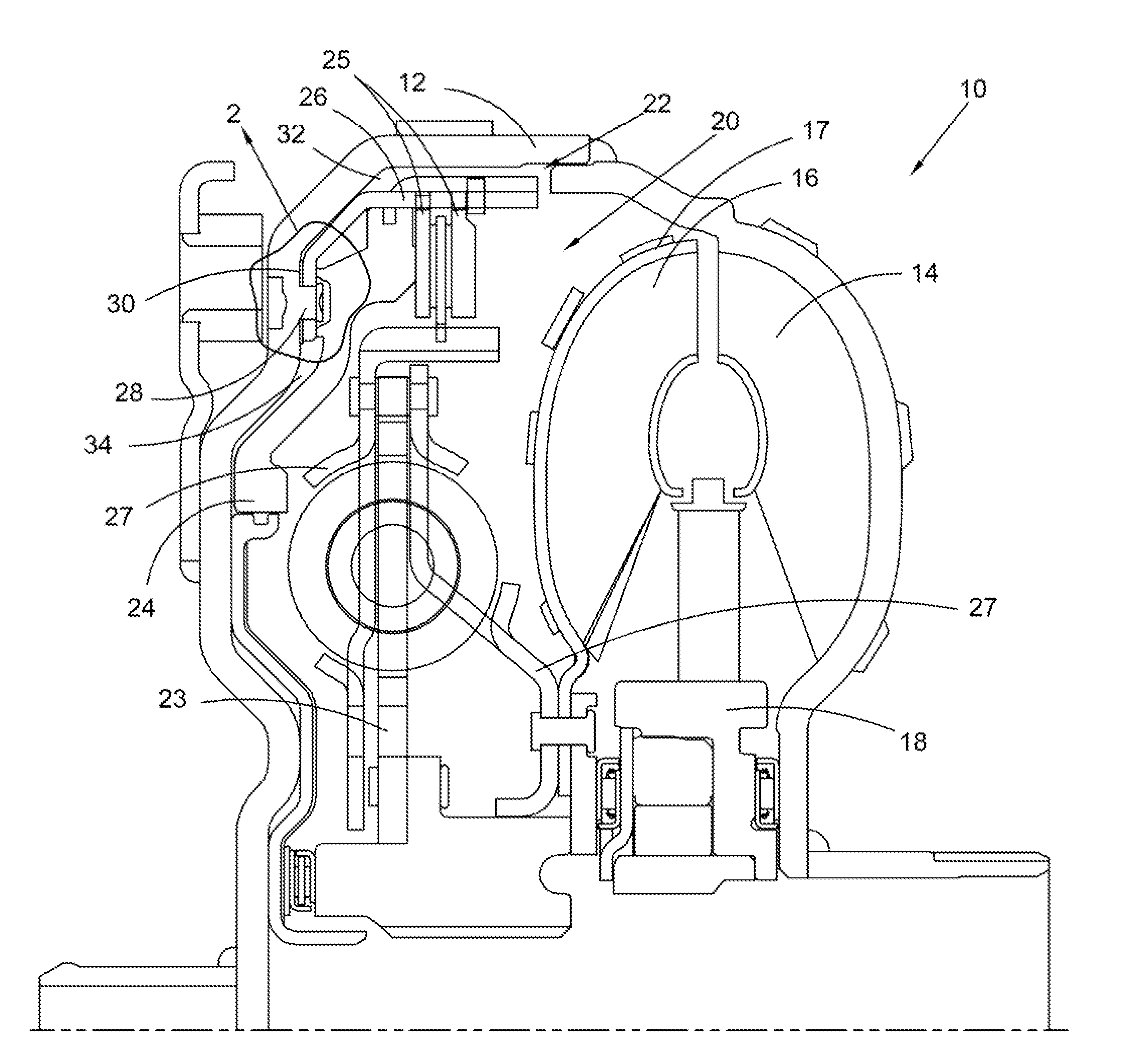
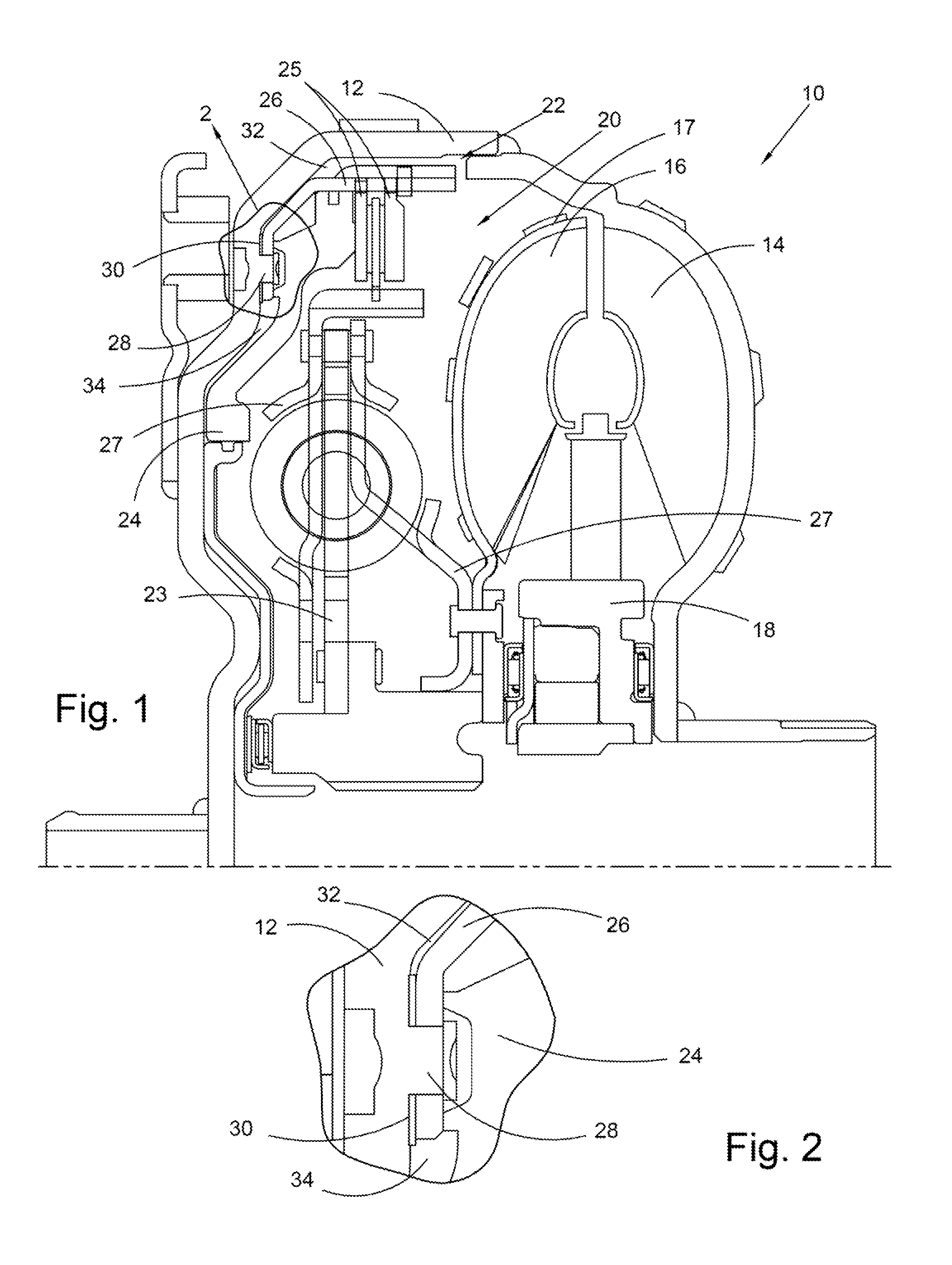
[0010]At the outset, it should be appreciated that like drawing numbers on different drawing views identify identical, or functionally similar, structural elements of the invention. While the present invention is described with respect to what is presently considered to be the preferred aspects, it is to be understood that the invention as claimed is not limited to the disclosed aspects.

[0011]Furthermore, it is understood that this invention is not limited to the particular methodology, materials and modifications described and as such may, of course, vary. It is also understood that the terminology used herein is for the purpose of describing particular aspects only, and is not intended to limit the scope of the present invention, which is limited only by the appended claims. It is also understood that any reference to axial or radial directions or properties is made with respect to the axis of rotation shown in the drawings, located generally along the bottom of FIG. 1.

[0012]Unles...


PUM


Abstract

An assembly for a torque converter including a first component, a second component non-rotatably secured to the first component by a connection member, wherein a seal is arranged between the first and second components, and the connect member extends through the seal, and wherein the seal is made from a cellulose-based material, wherein the first and second components at least partially define a first chamber and a second chamber, and wherein the seal separates the first chamber from the second chamber in a substantially fluid-tight seal manner.

Description

CROSS-REFERENCE TO RELATED APPLICATIONS[0001]This application claims the benefit under 35 U.S.C. §119(e) of U.S. Provisional Application No. 61 / 425,422 filed Dec. 21, 2010 which application is incorporated herein by reference.FIELD OF THE INVENTION[0002]The invention broadly relates to torque converters, more specifically to clutches in torque converters, and even more particularly to a fluid-tight seal for improved operation of a clutch in a torque converter.BACKGROUND OF THE INVENTION[0003]Torque converters are well known in the art. Some torque converters, such as torque converters having a so-called three-pass clutch lockup design, include a clutch plate retainer that is attached to the cover of the torque converter. The retainer carries and transfers torque to clutch plates. The attachment of such retainers in prior art torque converters involved welding the retainer to the cover or attaching the retainer without any special sealing element or process. For example, see U.S. Pat...

Claims


Application Information

Patent Timeline
Patent Type & Authority Applications(United States)
IPC IPC(8): F16H45/02
CPCF16H45/02F16H2045/0278F16H2045/0247F16H2045/021
Inventor AVINS, DAVID C.
Owner SCHAEFFLER TECH AG & CO KG
Learn More