

Illuminator allowing a wide luminous intensity distribution
- Summary
- Abstract
- Description
- Claims
- Application Information
AI Technical Summary
Benefits of technology
Problems solved by technology
Method used
Image

Examples
Embodiment Construction
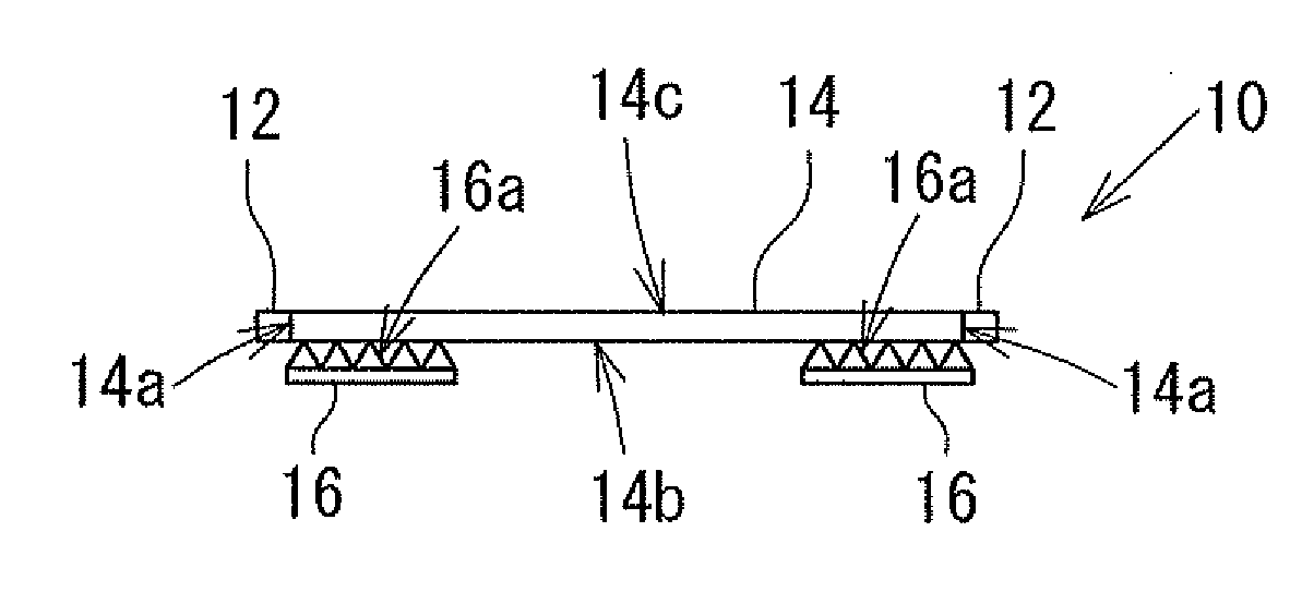
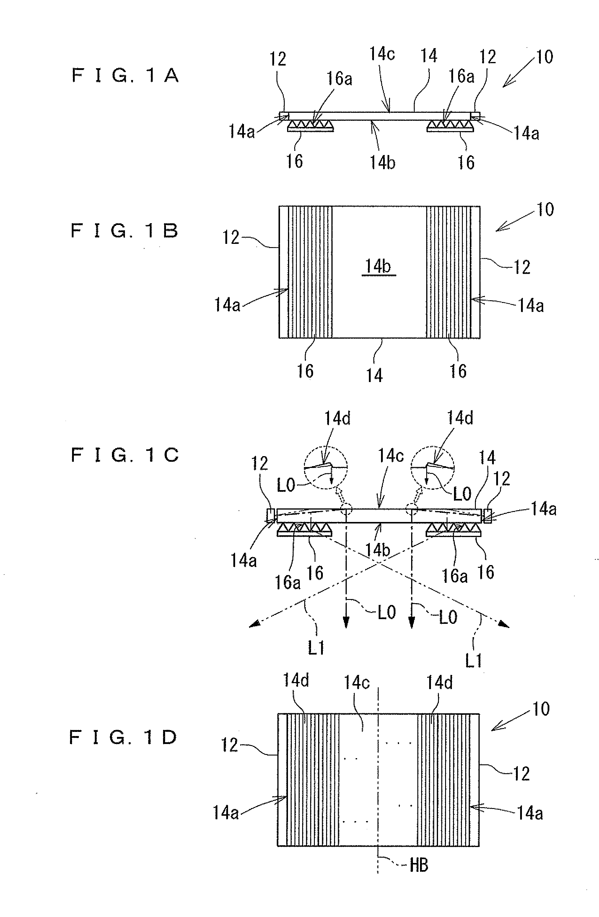
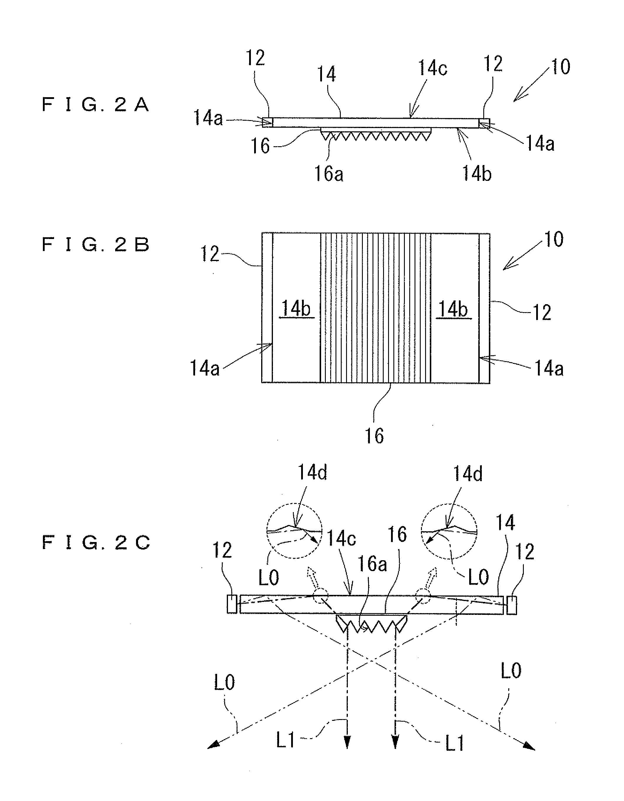
[0043]Hereinafter, some embodiments of the present invention will be explained with reference to the accompanied drawings. Here, portions identical with or corresponding to prior arts will be indicated with the same reference numerals, and the detail explanations thereof will be omitted. An illuminator 10 according to the embodiments of the present invention is composed of a light source unit 12, a light guide plate 14, and a prism body 16. Here, the light source unit 12 is linearly illustrated in FIG. 1B for convenience. However, in an actual situation, this means that a plurality of LEDs (that is, point light sources) are arranged. Further, this illuminator 10 includes an electric substrate that supplies current to the light source unit 12, and a cover contributing to the designability of the illuminator 10. Illustration of these parts is however omitted.
[0044]The light guide plate 14 is formed by which transparent resin materials such as polycarbonate resin, etc. are shaped into ...
PUM
 Abstract
Description
Claims
Application Information