Blower fan

Active Publication Date: 2012-06-28
ZHONGSHAN BROAD OCEAN MOTOR MFG
View PDF3 Cites 7 Cited by
  • Summary
  • Abstract
  • Description
  • Claims
  • Application Information

AI Technical Summary

Benefits of technology

[0008]In view of the above-described problems, it is one objective of the invention to provide a blower fan that can evenly

Problems solved by technology

1) because the motor has a certain weight, such two structures cannot satisfactorily transfer the weight to the fan housing; therefore, the stress is relatively centralized. When the motor works, it would produce large vibration and no

Method used


Image

  • Blower fan
  • Blower fan
  • Blower fan

Examples


Example

[0025]For further illustrating the invention, experiments detailing a blower fan are described below. It should be noted that the following examples are intended to describe and not to limit the invention.

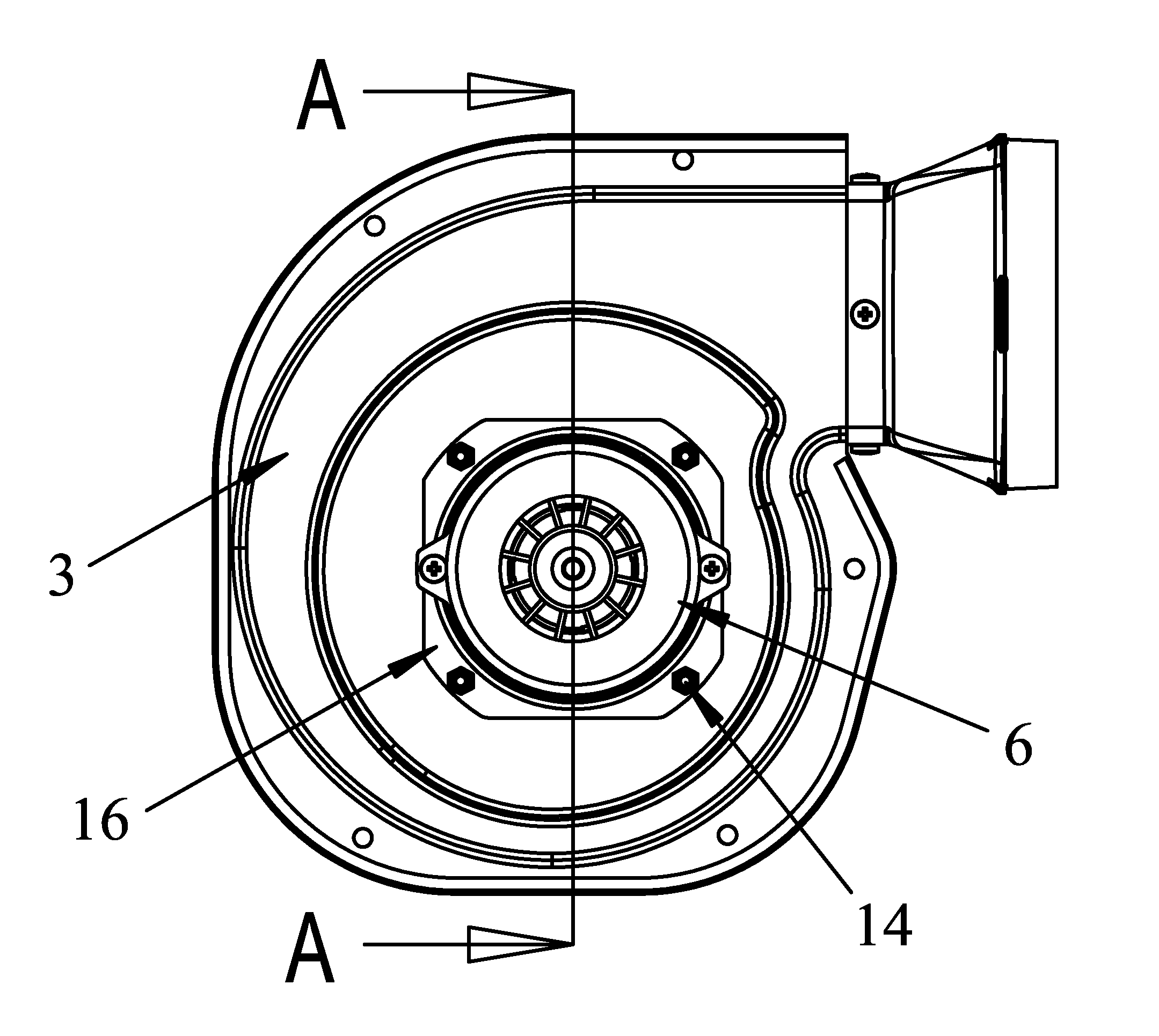
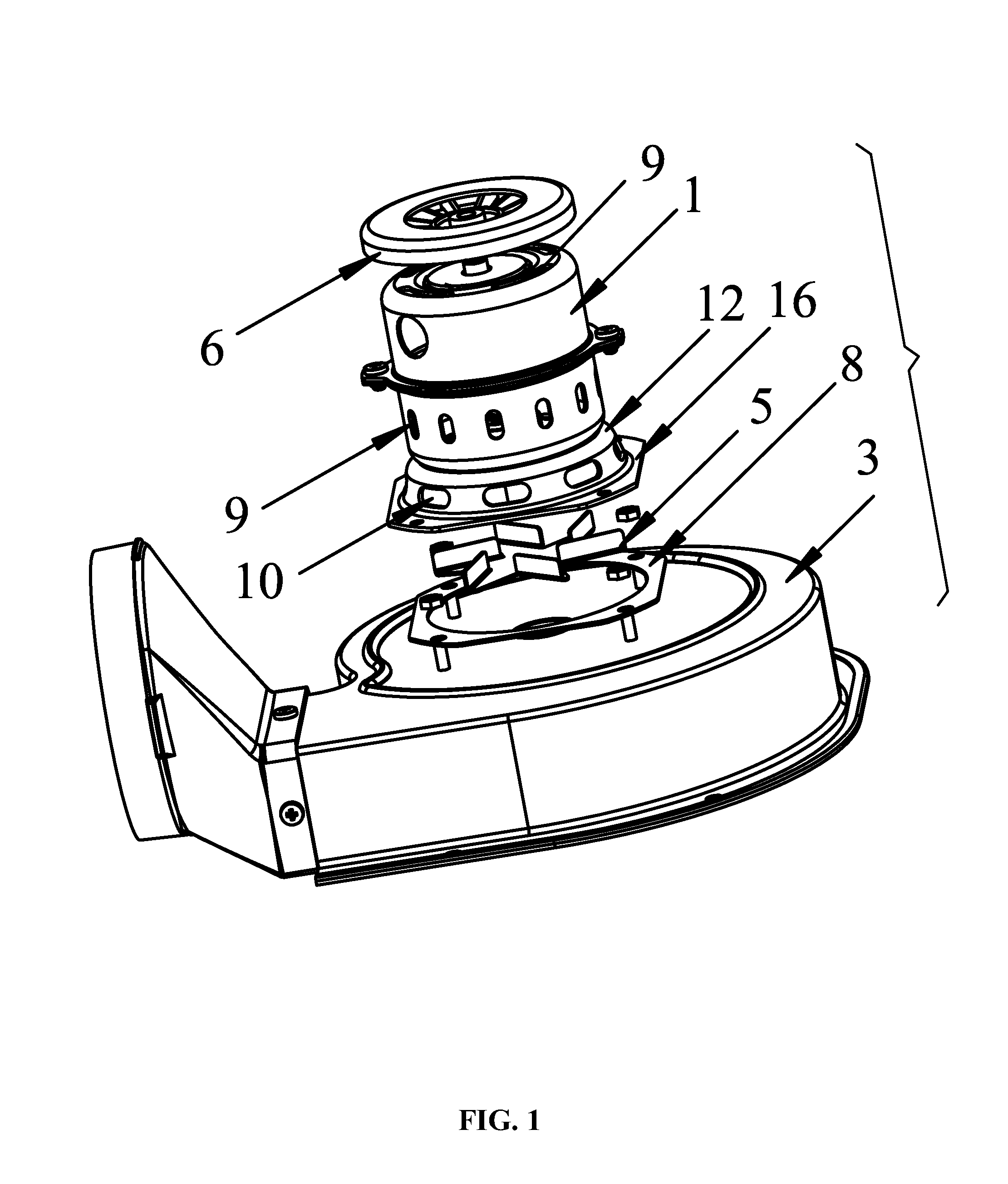
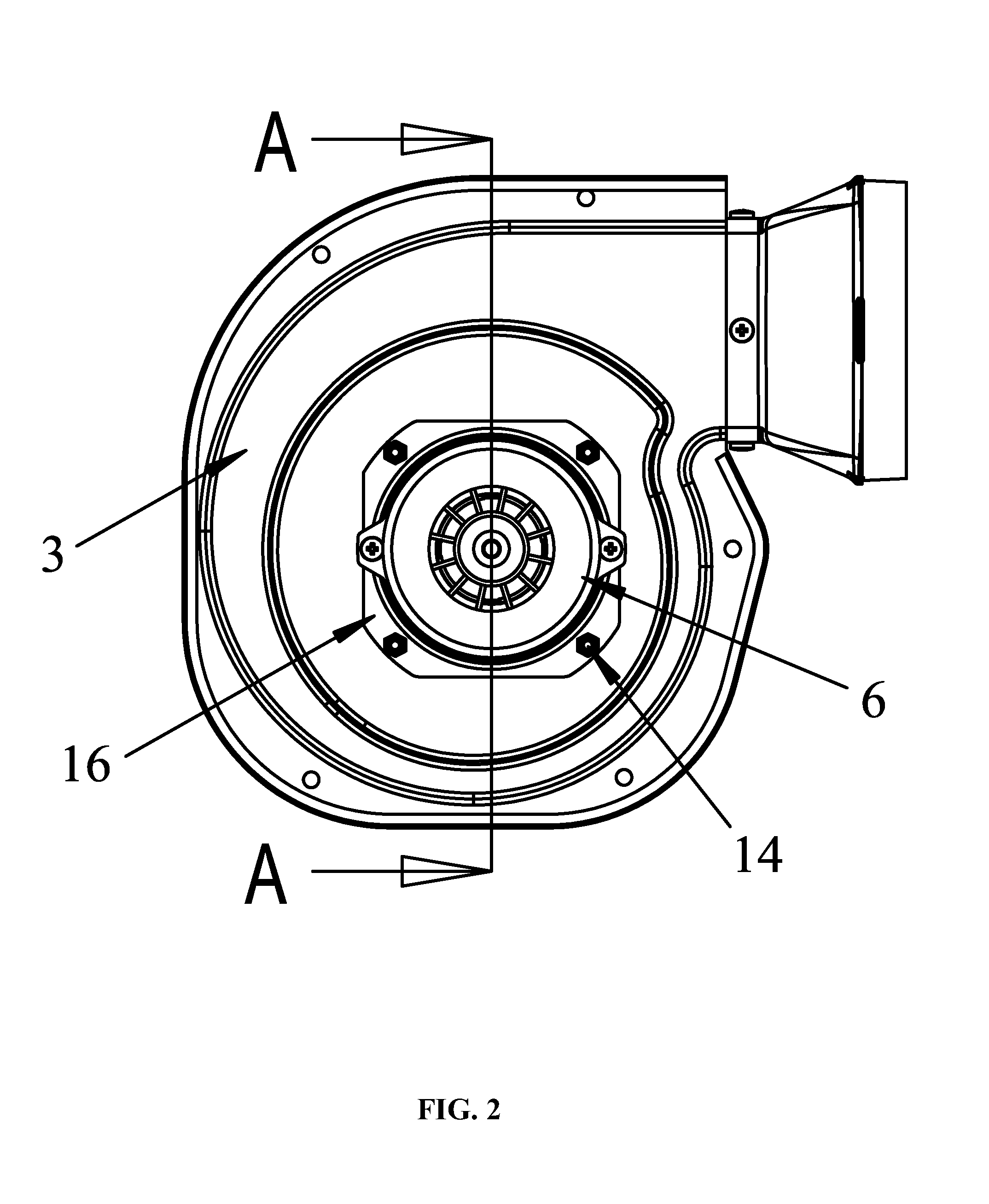
[0026]As shown in FIGS. 1-4, a blower fan comprises a motor 1 comprising a rotating shaft 7, a bracket, a fan housing 3 comprising a cavity 2, a fan wheel 4, and fan blades 5. The motor 1 is disposed on the fan housing 3 by means of the bracket. The extended portion of the rotating shaft 7 extends into the cavity 2 of the fan housing 3 and connects with the fan wheel 4. The fan blades 5 are disposed on the rotating shaft 7 and between the motor 1 and the fan housing 3. On the casing of the motor 1 is disposed with air vents 9. The bracket forms an annular side wall 12, and a cavity 13 is formed inside the annular side wall 12. The annular side wall 12 is disposed with air outlets 10, the air outlets 10 are connected with the cavity 13 of the annular side wall 12 and the fan blades ...


PUM


Abstract

A blower fan including a motor having a rotating shaft, a bracket, a fan housing having a cavity, a fan wheel, and fan blades. The motor is disposed on the fan housing via the bracket. An extended portion of the rotating shaft extends into the cavity of the fan housing and connects with the fan wheel. The fan blades are disposed on the rotating shaft and between the motor and the fan housing. On the casing of the motor is disposed with air vents. The bracket forms an annular side wall. A cavity is formed inside the annular side wall. The annular side wall is outfitted with air outlets which are connected with the cavity of the annular side wall and the fan blades are disposed in the cavity.

Description

CROSS-REFERENCE TO RELATED APPLICATIONS[0001]This application is a continuation of International Patent Application No. PCT / CN2010 / 077665 with an international filing date of Oct. 12, 2010, designating the United States, now pending, and further claims priority benefits to Chinese Patent Application No. 200920295875.3 filed Dec. 25, 2009, and to Chinese Patent Application No. 200920295851.8 filed Dec. 25, 2009. The contents of all of the aforementioned applications, including any intervening amendments thereto, are incorporated herein by reference.BACKGROUND OF THE INVENTION[0002]1. Field of the Invention[0003]The invention relates to a blower fan.[0004]2. Description of the Related Art[0005]A conventional blower fan includes a motor, a bracket, fan blades, a fan housing, and a fan wheel, in which the motor is disposed on the fan housing by means of the bracket, an extended portion of a motor rotating shaft extends into a cavity of the fan housing and connects with the fan wheel, an...

Claims


Application Information

Patent Timeline
IPC IPC(8): F04D29/40F04D25/02
CPCF04D25/0606F04D25/082F04D29/668F04D29/603F04D13/06F04D29/5806
Inventor LIU, XIANGLU, PINGZHANG, MIAO
Owner ZHONGSHAN BROAD OCEAN MOTOR MFG
Why Eureka
Try Eureka