

Ultrasonic Measurement Waveguide Rod and Ultrasonic Measurement Instrument
- Summary
- Abstract
- Description
- Claims
- Application Information
AI Technical Summary
Benefits of technology
Problems solved by technology
Method used
Image

Examples
embodiment 1
(1) Embodiment 1
[0039]Hereunder, a description is given for an embodiment 1 of the present invention with reference to FIG. 1 to FIG. 11.
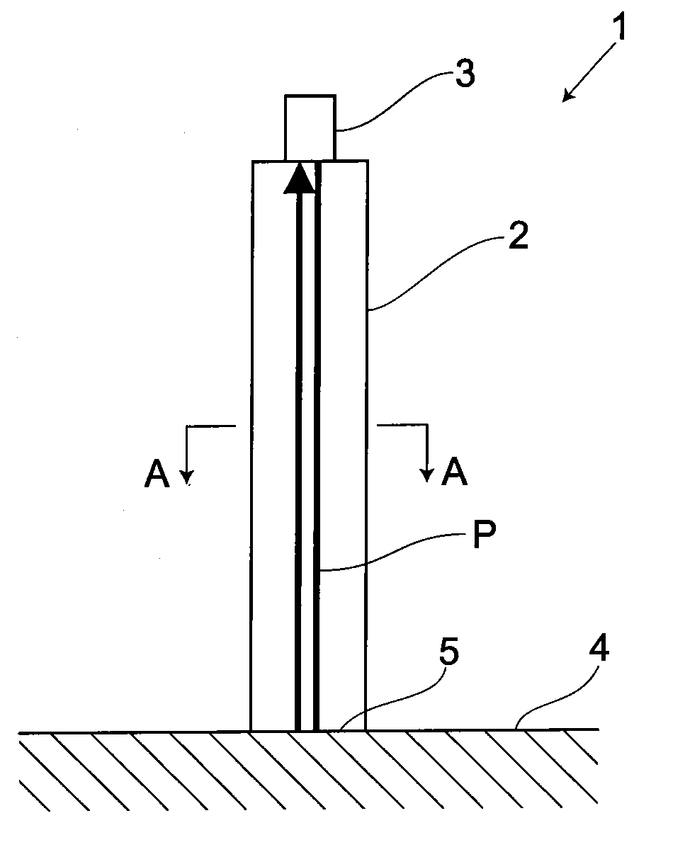
[0040]As shown in FIG. 1, an ultrasonic flaw detection instrument 1, serving as an ultrasonic measurement instrument, includes an ultrasonic flaw detection waveguide rod 2, serving as an ultrasonic measurement waveguide rod 2, and a probe 3 for acting as an ultrasonic transmitting and receiving unit, thus conducting an ultrasonic flaw detection test on various test pieces 4.
[0041]The probe 3 is arranged via a contact medium on one axial end of the waveguide rod 2 to come in contact with the one end. The ultrasonic probe 3 includes a vibrator (not shown) for generating an ultrasonic pulse and allows an ultrasonic wave emitted from the vibrator to enter a test piece via the waveguide rod 2 and then detects a returned ultrasonic wave. So, the ultrasonic probe 3 is equipped with functions of a wave transmission means and wave reception means. An ultras...
embodiment 2
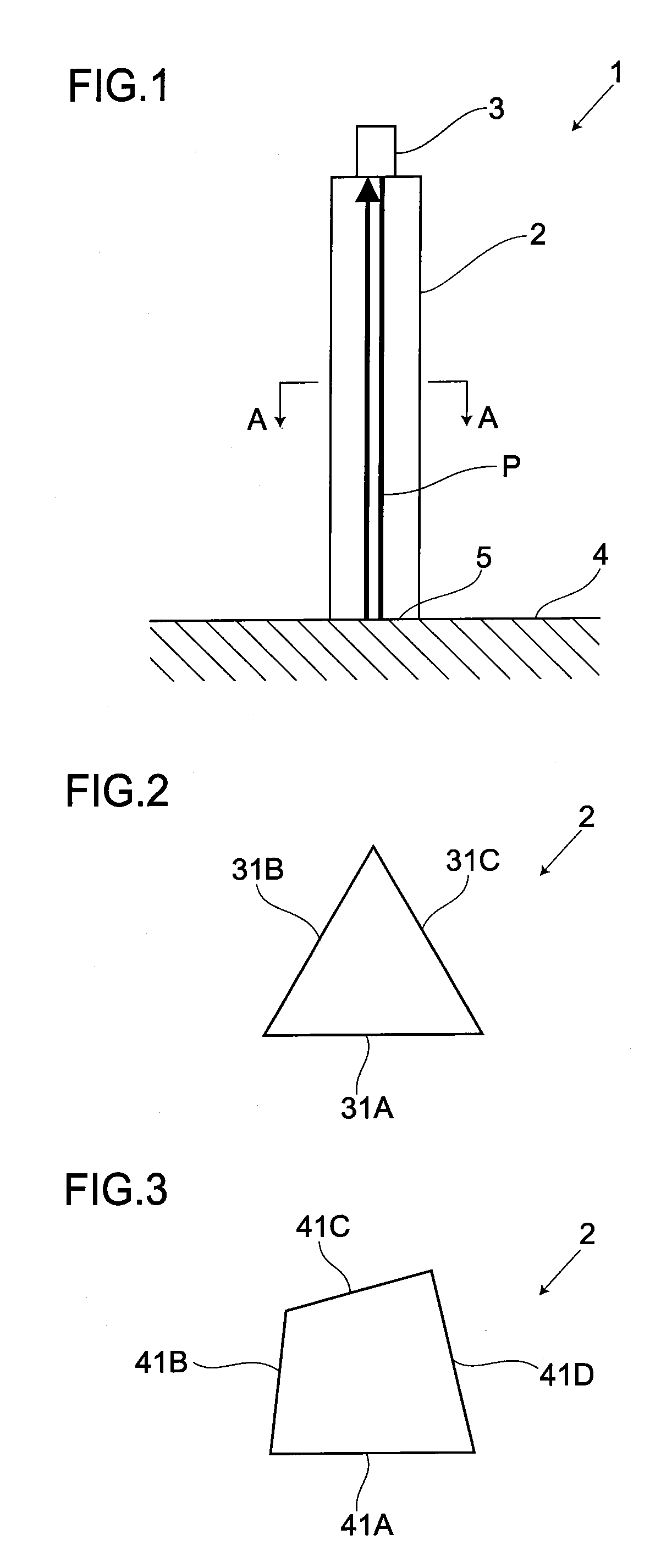
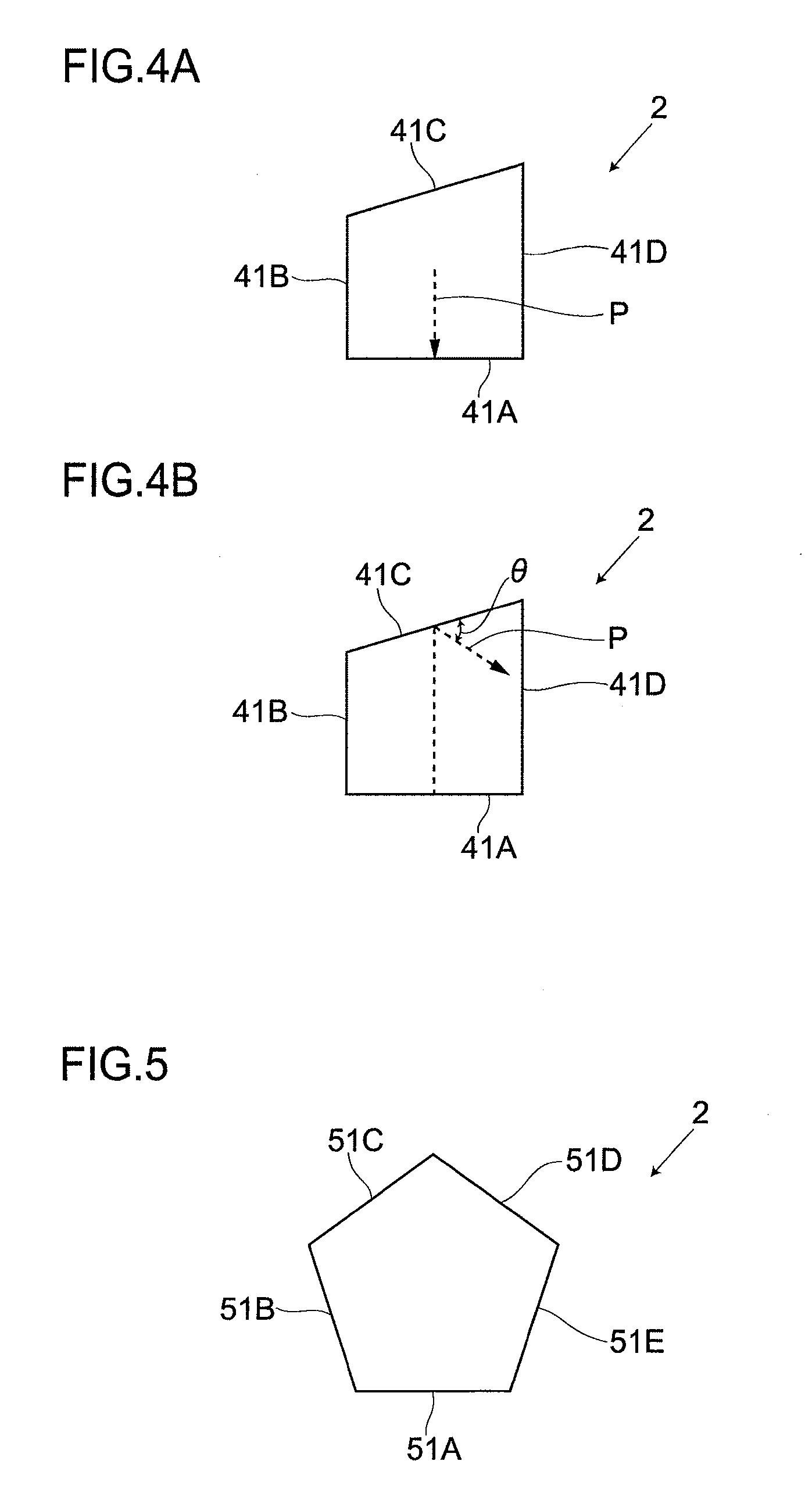
[0076]FIG. 12 shows an embodiment 2 of the present invention. Then, parts the same as in the embodiment 1 are attached with the same symbols and a detailed description thereof is given with the descriptions of the same part omitted. In this embodiment, a cross-sectional shape is formed of the same shape of a polygon in part of a length L and is formed of a tapered polygon diminishing toward the other end in cross-sectional area. Besides, the cross-sectional shape in the part of the tapered polygon is formed of a homothetic shape.
[0077]Further, as described above, in the present embodiment, the cross-sectional shape is the same in the part in the axial direction. Hence, in the part of the axial direction, an ultrasonic wave reflects off the outer surfaces not parallel to one another, thus enabling a noise echo to be prevented from arising.
[0078]Furthermore, as described above, in the present embodiment, the cross-sectional shape is formed of a homothetic shape in the part of or the e...
embodiment 3
[0080]FIG. 13 shows a third embodiment of the present invention. Then, parts the same as in the above embodiments are attached with the same symbols and a detailed description is given with the descriptions of the same parts omitted. In this embodiment, the waveguide rod 2 is formed of, e.g., a regular pentagon, as a polygon. The corners of the cross-sectional shape are formed with a cutout portion 11 subjected to a chamfering process and is formed with an R-shape-processed portion 12 subjected to an R forming process. In this case, the cross-sectional shape is unchanged as a pentagon. Although the embodiments of the present invention are described in detail above, the present invention is not limited to the above embodiments and various modifications are possible within the scope of the gist of the invention. The shape of a polygon, for example, does not need to be precise but may be of an approximate polygon. Further, the present invention is not limited to the use for ultrasonic ...
PUM
 Abstract
Description
Claims
Application Information