Support device for stopper of bathroom sink or tub

Active Publication Date: 2019-07-18
CHEN CHIH WEI
View PDF0 Cites 0 Cited by
  • Summary
  • Abstract
  • Description
  • Claims
  • Application Information

AI Technical Summary

Benefits of technology

[0006]The present invention relates to a stopper of a bathroom sink or tub, and comprises a base part having a cylindrical room defined therein and the base part has a drain hole defined through the bottom thereof. The base part is connected to a sink or a tub. A shank is removably connected to the base part and partially located in the room. A cap has a flange extending radially therefrom, and a tubular portion extends from the underside of the cap. The top end of the shank is connected to the tubular portion. A connection portion is formed on the underside of the flange. A seal part is connected to the connection portion and has a support rin

Problems solved by technology

When pulling the cap 50 to form the gap to drain the water, the air in the sink or tub may cause the ou

Method used


Image

  • Support device for stopper of bathroom sink or tub
  • Support device for stopper of bathroom sink or tub
  • Support device for stopper of bathroom sink or tub

Examples


Embodiment Construction

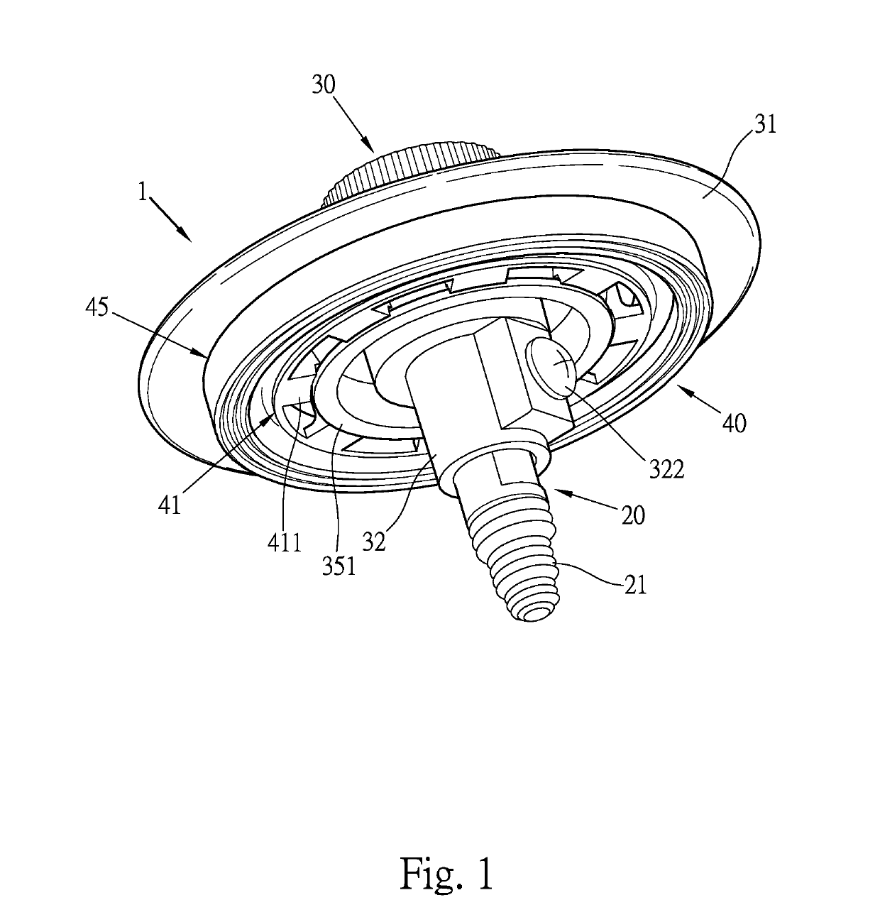
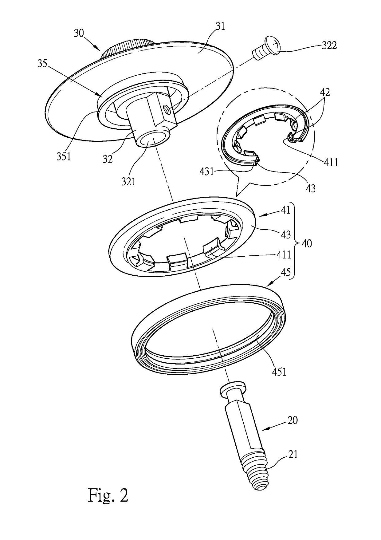
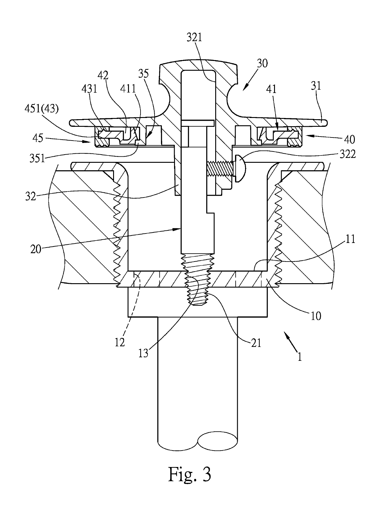
[0013]Referring to FIGS. 1 and 2, the stopper 1 of the present invention comprises a base part 10 that is connected to a sink or a tub, and the base part 10 has a cylindrical room 11 defined therein. The base part 10 has an open top and multiple drain holes 12 defined through the bottom thereof. The drain holes 12 communicate with the drain pipe. A shank 20 includes a threaded end 21 at the lower end thereof and the threaded end 21 is threadedly and removably connected to the threaded hole 13 of the base part 10. The shank 20 is partially located in the room 11. A cap 30 is connected to the top end of the shank 20 and a seal part 40 is connected to the underside of the cap 30. When the cap 30 and the seal part 40 are moved upward and downward, the seal part 40 opens and seal the base part 10.

[0014]The cap 30 has a flange 31 extending radially therefrom, and a tubular portion 32 extends from the underside of the cap 30. The tubular portion 32 of the cap 30 has a recess 321 defined in...


PUM


Abstract

A stopper of a bathroom sink or tub includes a shank removably connected to a base part which is connected to the sink or tub and has a drain hole. A cap is connected to the shank and has a flange that extends radially from the cap. A connection portion is formed on the underside of the flange. A seal part is connected to the connection portion and includes a support ring and a collar. The support ring has at least one hook member formed in the inner periphery thereof so as to be connected to the connection portion of the cap. A positioning portion extends from radially from the support ring. The collar is a rubber collar and has a groove in the inner periphery thereof. The positioning portion of the support ring is engaged with the groove to prevent the collar from deformation and generating noise.

Description

BACKGROUND OF THE INVENTION1. Fields of the invention[0001]The present invention relates to a stopper, and more particularly, to a support device of the stopper of a bathroom sink or tub, and the stopper is operated silently.2. Descriptions of Related Art[0002]The conventional stopper of a bathroom sink or a tub is disclosed in FIG. 4 and includes a cap 50, a seal plate 52 connected to the cap 50, a shank 60 to which the cap 50 is connected, and a base part 70 which is secured to the drain hole of the sink or the tub. The base part 70 includes a room 71 and the drain hole 711 is defined in the inner bottom of the base part 70. The shank 60 includes a threaded end 61 which is threadedly connected to the threaded hole 72 in the base part 70. The top end of the shank 60 is connected to the underside of the cap 50. The seal plate 52 is a rubber plate and connected to the bottom of the cap 50.[0003]When the user operates the cap 50 to move the seal plate 52 along the shank 60, the cap 50...

Claims


Application Information

Patent Timeline
IPC IPC(8): A47K1/14E03C1/23
CPCA47K1/14E03C1/2306E03C2201/60
Inventor CHEN, CHIH-WEIKUO, KUANG-MING
Owner CHEN CHIH WEI
Why Eureka
Try Eureka