Liquid crystal display apparatus and liquid crystal television

Inactive Publication Date: 2014-11-13
SHARP KK
View PDF7 Cites 13 Cited by
  • Summary
  • Abstract
  • Description
  • Claims
  • Application Information

AI Technical Summary

Benefits of technology

[0029]In accordance with the liquid crystal display apparatus and the liquid crystal television a

Problems solved by technology

In this case, when the held and pressed optical sheet suffers from a deformation, the optical sheet is deformed,

Method used


Image

  • Liquid crystal display apparatus and liquid crystal television
  • Liquid crystal display apparatus and liquid crystal television
  • Liquid crystal display apparatus and liquid crystal television

Examples


Example

Embodiment 1

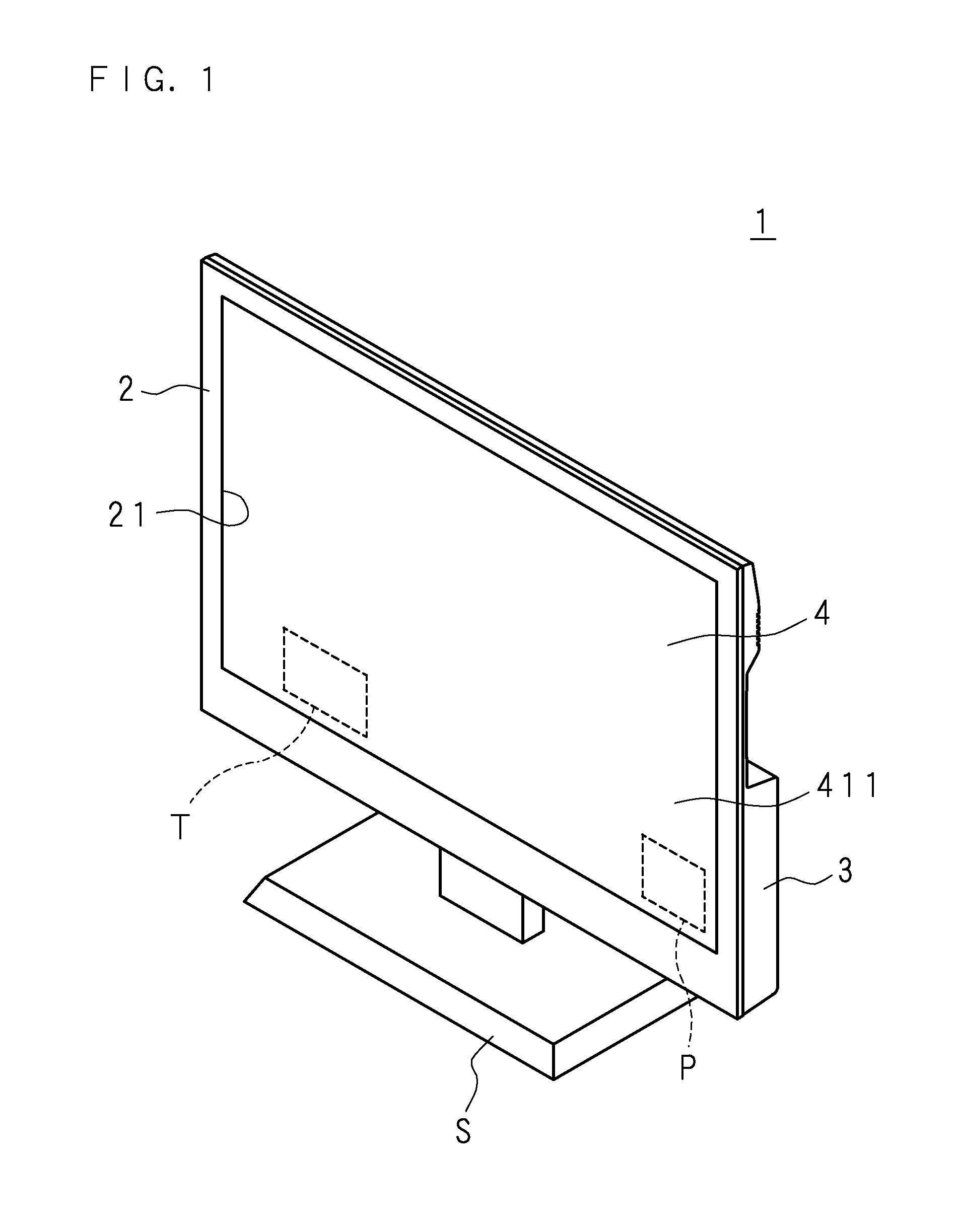
[0057]FIG. 1 is a schematic perspective view of a liquid crystal television 1. Herein, when a viewer faces a screen 411 that displays an image by the liquid crystal television 1, the viewer side of the screen 411 will be referred to as a front side and the inward side of the screen 411, which is the opposite side thereof, will be referred to as a back or rear side. The screen 411 has a laterally long and substantially rectangular shape, and from a viewer's position of facing the screen 411, the right side of the screen 411 in a longitudinal direction thereof will be referred to as right and the left side of the screen 411 in the longitudinal direction will be referred to as left. When facing the back side of the liquid crystal television 1, the left and right are inverted with the left and right of the front side. Further, from a viewer's position of facing the screen 411, the upper side of the screen 411 in a lateral direction thereof will be referred to as top and the ...

Example

Embodiment 2

[0168]Embodiment 2 relates to a configuration in which a support part is provided on the discharge prevention frame (a frame body) 40 to support the light guide plate 43. The light guide plate 43 is sandwiched by the support part of the discharge prevention frame 40 located on the front and the backlight chassis 45 located on the back.

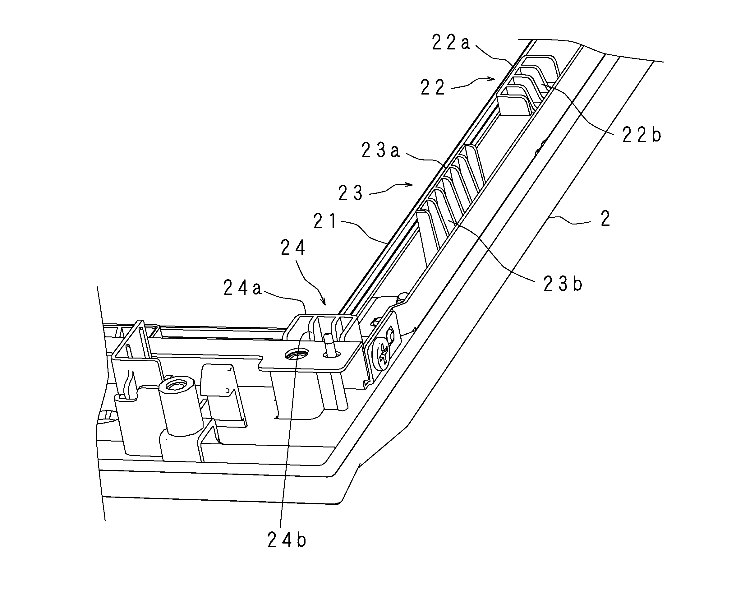
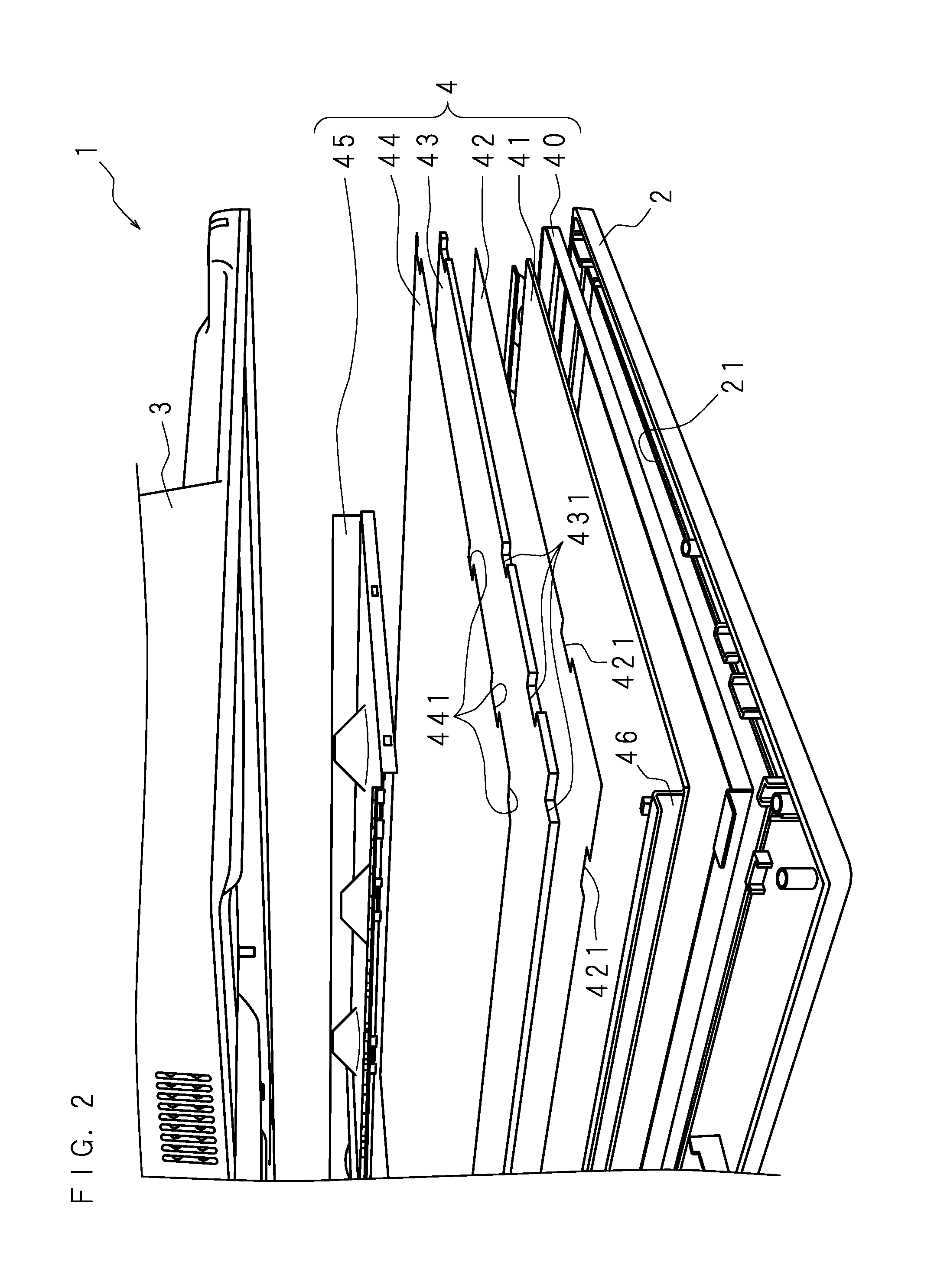
[0169]The discharge prevention frame 40 is a frame located between the front cabinet 2 on the front side and the liquid crystal panel 41 on the back side (see FIG. 2). The discharge prevention frame 40 has a size overlapping the plurality of first ribs 22, second ribs 23 and partition ribs 24 with each other, which are provided on the back side of the front cabinet 2 (see FIGS. 15A and 15B).

[0170]FIG. 16 is a rear view of the discharge prevention frame 40. The discharge prevention frame 40 is formed by pressing a metal material, for example. The discharge prevention frame 40 includes a cylindrical outer frame, and a flange-shaped inner fram...


PUM


Abstract

A liquid crystal panel module includes a liquid crystal panel, an optical sheet and a light guide plate, which are sequentially laminated from the front side to the back side. A front cabinet is provided with an opening through which a screen of the liquid crystal panel is viewed. The front cabinet includes first ribs formed around the opening on a back face thereof and second ribs formed around the opening on the back face thereof further away from the opening than the first ribs. The first ribs are higher than a total thickness of the liquid crystal panel and the optical sheet, and the second ribs are higher than a total thickness of the liquid crystal panel, the optical sheet and the light guide plate. The liquid crystal panel is housed in an area surrounded by the first ribs. The optical sheet is housed in an area surrounded by the first ribs or the second ribs. The light guide plate is housed in an area surrounded by the second ribs, and a front peripheral edge part thereof abuts a tip end face of the first ribs.

Description

CROSS-REFERENCE TO RELATED APPLICATIONS[0001]This non-provisional application is a National Stage entry under U.S.C. §371 of International Application No. PCT / JP2012 / 073592 filed on Sep. 14, 2012, which claims the priorities of Japanese Patent Application No. 2011-272666 filed in Japan on Dec. 13, 2011 and Japanese Patent Application No. 2012-147508 filed in Japan on Jun. 29, 2012. The entire contents of all of the above applications are hereby incorporated by reference.FIELD[0002]The present invention relates to a liquid crystal display apparatus including a liquid crystal panel module and to a liquid crystal television.BACKGROUND[0003]Each component such as a liquid crystal panel, an optical sheet, a light guide plate, or the like, which are included in an edge light type liquid crystal panel module, is fixed thereto by using frame-shaped bezels.[0004]Japanese Patent Application Laid-Open No. H11-337937 discloses a liquid crystal display apparatus in which the each component is po...

Claims


Application Information

Patent Timeline
IPC IPC(8): G02F1/1333H04N5/64
CPCG02F1/133308H04N5/64G02F2001/133314G02F2001/13332G02F1/133314G02F1/133317G02F1/133322G02F1/133325H04N5/66G02F1/13332
Inventor ITO, KEITA
Owner SHARP KK
Why Eureka
Try Eureka