Insert molding method and insert molded product

Inactive Publication Date: 2011-06-16
HITACHI CABLE
View PDF14 Cites 13 Cited by
  • Summary
  • Abstract
  • Description
  • Claims
  • Application Information

AI Technical Summary

Benefits of technology

[0024]According to one embodiment of the invention, an insert molding method is devised such that, when filling with an insulating resin, bus bars can move over the whole length by pressure of the filed resin. Hence, since pressure difference that may cause deformation of the bus bars is not generated duri

Problems solved by technology

However, in the conventional insert molding method, the laminated (separately held) bus bars may be pushed by the resin filled into the molding die during the molding such that they are deformed by the molding.
This may

Method used


Image

  • Insert molding method and insert molded product
  • Insert molding method and insert molded product
  • Insert molding method and insert molded product

Examples


Example

First Embodiment

Without Supporting Member

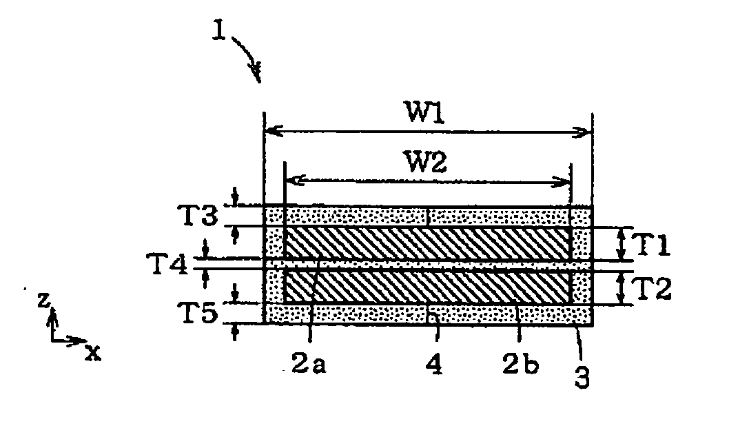
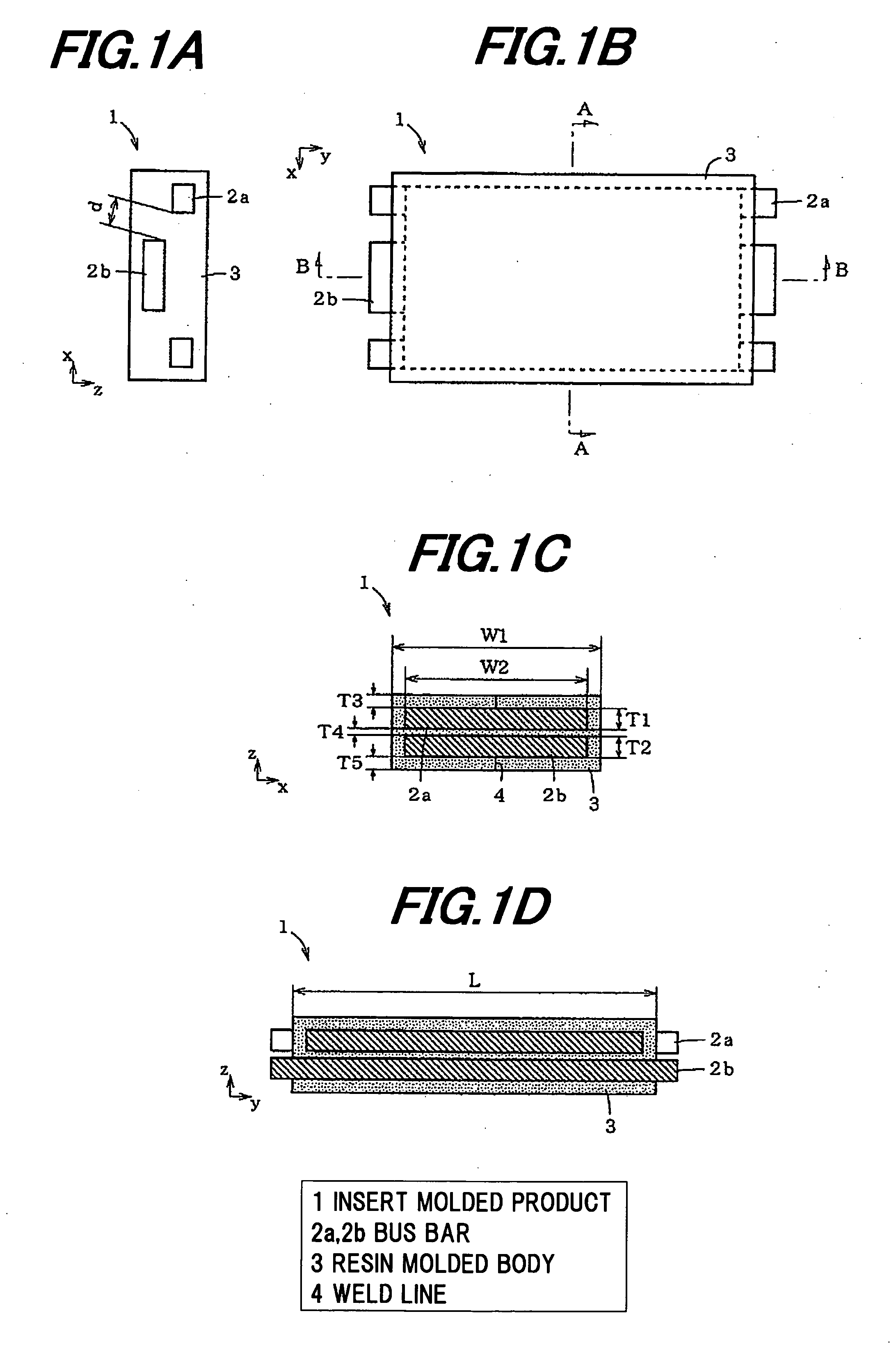
[0050]FIG. 1 are views showing an insert molded product in a first embodiment of the invention, wherein FIG. 1A is a side view, FIG. 1B is a plan view, FIG. 1C is a cross sectional view taken on line A-A (horizontal cross sectional view) and FIG. 1D is a cross sectional view taken on line B-B (vertical cross sectional view).

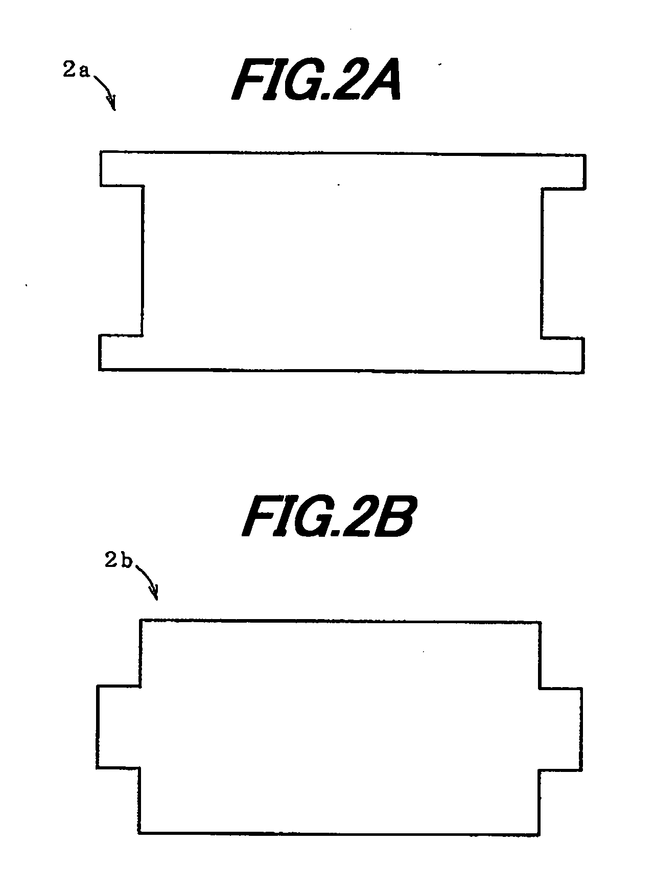
[0051]As shown in FIG. 1, an insert molded product 1 in the first embodiment is composed of bus bars (conductors) 2a and 2b as plural (two in the drawing) inset members separately arranged at a set interval, and a resin molded body 3 for covering the gap between the bus bars 2a and 2b as well as the periphery thereof. Here, the set interval is a distance by which electrical insulation between the bus bars 2a and 2b is well maintained, and which is a design matter naturally taken into consideration for forming the insert molded product 1.

[0052]In FIG. 1, T1 and T2 respectively denote thicknesses of the bus bars 2a and 2b, T...

Example

Second Embodiment

With a Supporting Member Near the Center

[0079]The insert molding method in the second embodiment is different from that in the first embodiment in that a supporting member 10 which contacts with the bus bars 2a and 2b along the length direction is inserted into the molding die 5, and then, the supporting member 10 is separated from the bus bars 2a and 2b so as not to disturb the intrusion of the insulating resin 9 when the insulating resin 9 is intruded into the inner rim portion of the molding die 5.

[0080]The reason for inserting the supporting member 10 into the molding die 5 will be described below.

[0081]The both ends of the bus bars 2a and 2b in a y-axis direction (length direction) are restricted by the holding groove 6 so that the separation interval T4 between the bus bars 2a and 2b is not extended more than a certain length (T6+T4+T7−(T1+T2)) and that the distances T3 and T5 from the bus bars 2a, 2b to the inner wall surface of the molding die 5 does not fal...

Example

Third Embodiment

With the Supporting Member on the Gate Side

[0084]The insert molding method in the third embodiment is different from that in the second embodiment in the position into which the supporting member 10 is inserted. That is, the supporting member 10 is inserted on the gate side in the third embodiment. The reason therefor will be described below.

[0085]If the insulating resin 9 is poured into the outer layer on the gate 8 side in the state that the small amount of the insulating resin 9 is poured into the inner layer, the force in a direction to narrow the separation interval T4 between the bus bars 2a and 2b acts due to the pressure of the insulating resin 9 of the outer layer, and it becomes difficult to pour the insulating resin 9 into the gap between the bus bars 2a and 2b. Such a phenomenon can be avoided by using the molding die 5 as shown in FIG. 11, where the bus bars 2a and 2b are pressed from the outside by the supporting member 10 on a side close to the gate 8....


PUM

PropertyMeasurementUnit
Lengthaaaaaaaaaa
Pressureaaaaaaaaaa
Widthaaaaaaaaaa

Abstract

An insert molding method includes holding a plurality of insert members in a molding die to be separated from one another, and subsequently filling a resin into the molding die to fill a gap between the insert members and a periphery thereof with the resin to form an insert molded product such that the insert members are separated at a preset interval from one another. The molding die includes a space-maintaining projection for maintaining a separation interval between the insert members at the preset interval or more, the projection being formed on an inner wall surface of the molding die opposite to a longitudinal end of the insert members, and a gate for filling the resin therethrough into the molding die, the gate being formed on an inner wall surface of the molding die opposite to a side of the insert members in a width direction thereof.

Description

[0001]The present application is based on Japanese Patent Application No. 2009-285468 filed on Dec. 16, 2009, the entire contents of which are incorporated herein by reference.BACKGROUND OF THE INVENTION[0002]1. Field of the Invention[0003]The invention relates to an insert molding method that a gap between plural insert members and peripheries thereof are simultaneously filled with a resin by insert molding, and to an insert molded product.[0004]2. Description of the Related Art[0005]An insert molded product formed by simultaneously filling a gap between plural insert members and peripheries thereof with a resin includes, e.g., a molded product formed by laminating bus bars with narrow gaps and then simultaneously filling a gap between the bus bars and a periphery thereof with an insulating resin in order to electrically insulate the bus bars from each other.[0006]The bus bars are separately held in a molding die, the insulating resin is subsequently filled into the molding die suc...

Claims


Application Information

Patent Timeline
IPC IPC(8): B32B27/34B29C45/14B32B27/38
CPCY10T428/2495B32B27/34B29C45/14467B29C33/12B29C45/14065B32B27/38Y10T428/31511Y10T428/31725
Inventor YAMAMOTO, SATOSHITANBA, AKIHIROKAGA, MASAFUMI
Owner HITACHI CABLE
Why Eureka
Try Eureka