Hybrid vehicle drive control device
- Summary
- Abstract
- Description
- Claims
- Application Information
AI Technical Summary
Benefits of technology
Problems solved by technology
Method used
Image
Examples
first embodiment
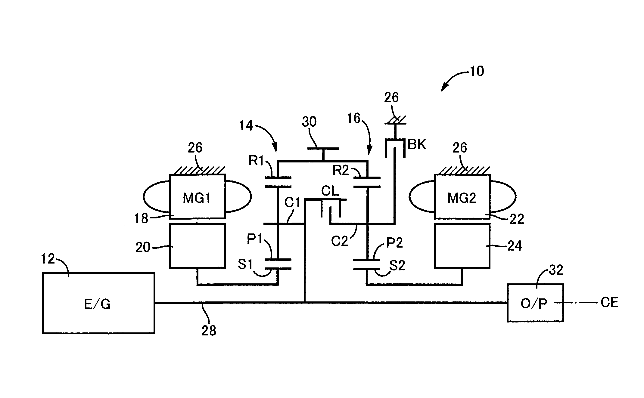
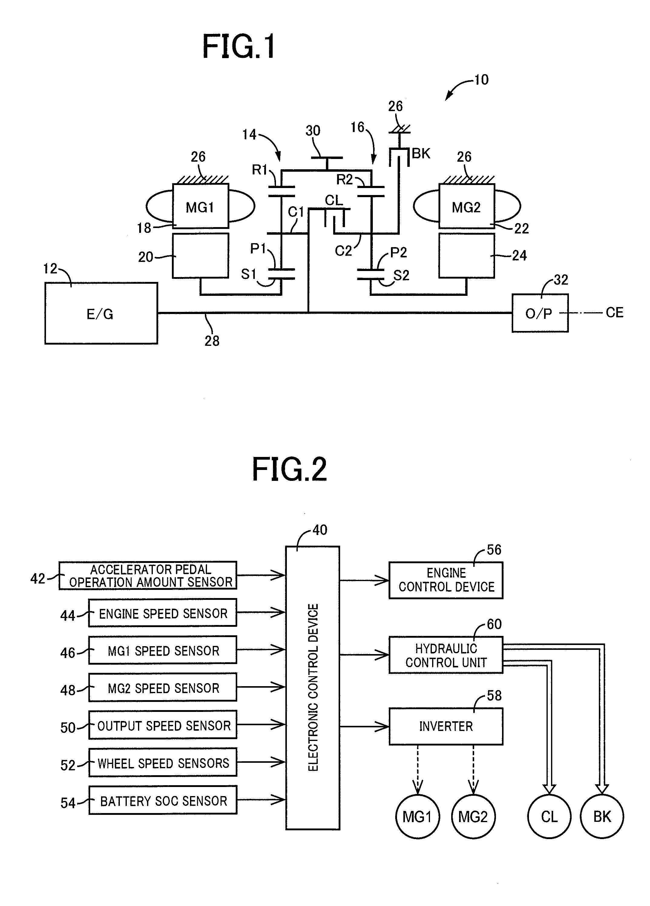
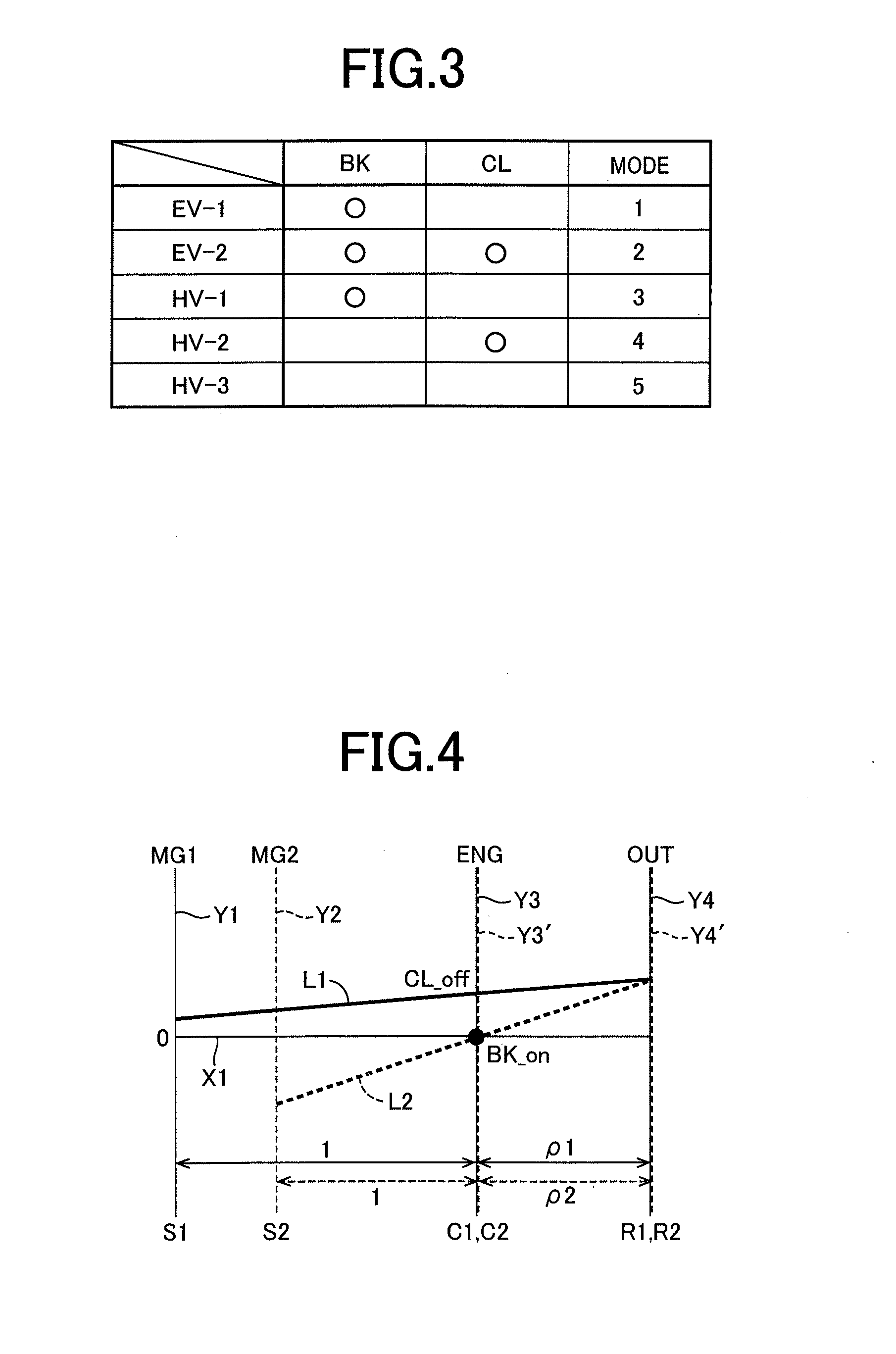
[0036]FIG. 1 is the schematic view for explaining an arrangement of a hybrid vehicle drive system 10 (hereinafter referred to simply as a “drive system 10”) to which the present invention is suitably applicable. As shown in FIG. 1, the drive system 10 according to the present embodiment is of a transversely installed type suitably used for an FF (front-engine front-drive) type vehicle, and is provided with a main vehicle drive power source in the form of an engine 12, a first electric motor MG1, a second electric motor MG2, a first differential mechanism in the form of a first planetary gear set 14, and a second differential mechanism in the form of a second planetary gear set 16, which are disposed on a common center axis CE. The drive system 10 is constructed substantially symmetrically with respect to the center axis CE. In FIG. 1, a lower half of the drive system 10 is not shown. This description applies to other embodiments which will be described.
[0037]The engine 12 is an inte...
second embodiment
[0076]FIGS. 12-17 are the schematic views for explaining arrangements of hybrid vehicle drive systems 100, 110, 120, 130, 140 and 150 according to another preferred embodiment of this invention. The present invention is equally applicable to the drive system 100 shown in FIG. 12 and the drive system 110 shown in FIG. 13, which have respective different orders of arrangement (position) of the first electric motor MG1, first planetary gear set 14, second electric motor MG2, second planetary gear set 16, clutch CL and brake BK, in the direction of the center axis CE. The prevent invention is also equally applicable to the drive system 120 shown in FIG. 14, wherein a one-way clutch OWC is disposed in parallel with the brake BK, between the carrier C2 of the second planetary gear set 16 and the stationary member in the form of the housing 26, such that the one-way clutch OWC permits a rotary motion of the carrier C2 relative to the housing 26 in one of opposite directions, and inhibits a...
third embodiment
[0077]FIGS. 18-20 are the collinear charts for explaining arrangements and operations of respective hybrid vehicle drive systems 160, 170 and 180 according to other preferred embodiments of this invention in place of the drive system 10. In FIGS. 18-20, the relative rotating speeds of the sun gear S1, carrier C1 and ring gear R1 of the first planetary gear set 14 are represented by the solid line L1, while the relative rotating speeds of the sun gear S2, carrier C2 and ring gear R2 of the second planetary gear set 16 are represented by the broken line L2, as in FIGS. 4-7. In the drive system 160 for the hybrid vehicle shown in FIG. 18, the sun gear S1, carrier C1 and ring gear R1 of the first planetary gear set 14 are respectively connected to the first electric motor MG1, engine 12 and second electric motor MG2, while the sun gear S2, carrier C2 and ring gear R2 of the second planetary gear set 16 are respectively connected to the second electric motor MG2 and output gear 30, and t...
PUM
 Abstract
Description
Claims
Application Information
 - R&D
- Intellectual Property
- Life Sciences
- Materials
- Tech Scout
- Unparalleled Data Quality
- Higher Quality Content
- 60% Fewer Hallucinations
Browse by: Latest US Patents, China's latest patents, Technical Efficacy Thesaurus, Application Domain, Technology Topic, Popular Technical Reports.
© 2025 PatSnap. All rights reserved.Legal|Privacy policy|Modern Slavery Act Transparency Statement|Sitemap|About US| Contact US: help@patsnap.com


