

Solar power generation system and power conditioner
- Summary
- Abstract
- Description
- Claims
- Application Information
AI Technical Summary
Benefits of technology
Problems solved by technology
Method used
Image

Examples
first preferred embodiment
[0042]Hereinafter, a first preferred embodiment of the present invention will be described.
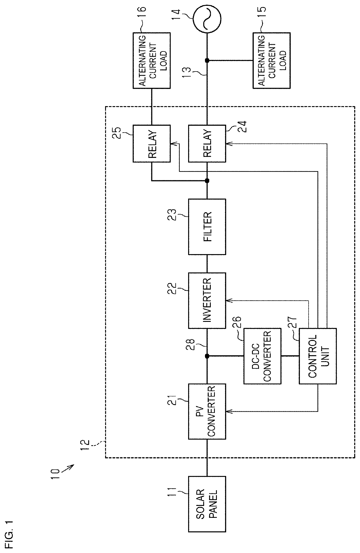
[0043]As illustrated in FIG. 1, a solar power generation system 10 of the present preferred embodiment preferably includes a solar panel 11 and a power conditioner 12 connected to the solar panel 11. In the present preferred embodiment, the power conditioner 12 is connected to a commercial power system 14 via a power line 13. The commercial power system 14 is preferably a distribution system with which an electric power company transmits power. A first alternating-current load 15 is connected to the power line 13. The first alternating-current load 15 is preferably, for example, an indoor load connected to a distribution board. The indoor load may be, for example, electrical equipment in an ordinary house such as a light, a refrigerator, a washing machine, an air conditioner, a microwave oven, or the like. Further, a second alternating-current load 16 is connected to the power conditioner 12. ...
modified example 1
[0105]As illustrated in FIG. 6, a solar power generation system 10a preferably includes the solar panel 11 and a power conditioner 12a connected to the solar panel 11. The power conditioner 12a is assumed to be for off-grid use and not linked with a power system and is connected to the first alternating-current load 15 corresponding to an autonomous load. The first alternating-current load 15 is, for example, an indoor load connected to a distribution board. The indoor load may be, for example, electrical equipment of an ordinary house such as, for example, a light, a refrigerator, a washing machine, an air conditioner, a microwave oven, or the like. The aforementioned first alternating-current load 15 may alternatively be electrical equipment in a commercial facility or a factory.
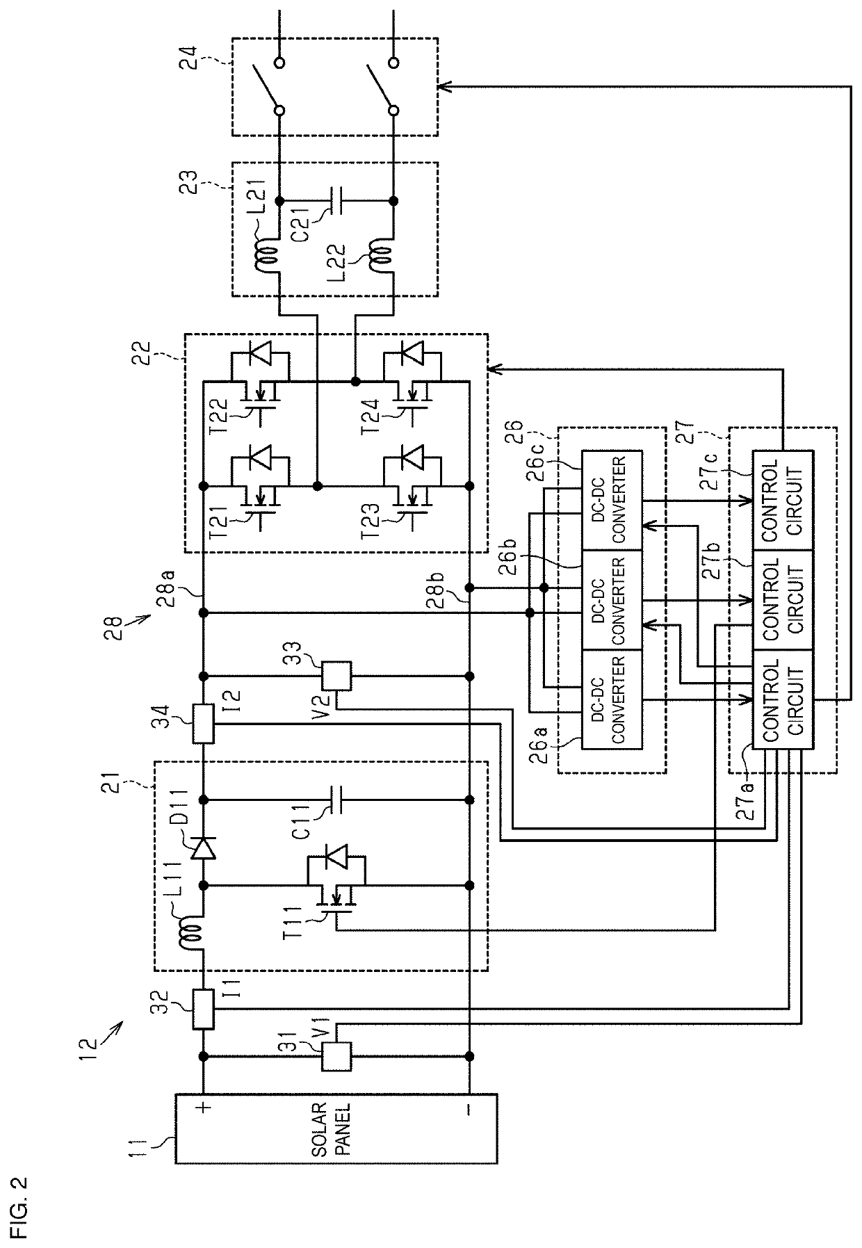
[0106]The power conditioner 12a includes the PV converter 21, the inverter 22, the filter 23, the first relay 24, the DC-DC converter 26, and the controller 27. The PV converter 21, the inverter 22, and th...
modified example 2
[0110]As illustrated in FIG. 7, a solar power generation system 10b preferably includes the solar panel 11 and a power conditioner 12b connected to the solar panel 11. In the present preferred embodiment, the power conditioner 12a is connected to the commercial power system 14 via the power line 13. The commercial power system 14 is a distribution system with which an electric power company transmits electric power. The first alternating-current load 15 is connected to the power line 13. In the present preferred embodiment, the first alternating-current load 15 is preferably, for example, an indoor load connected to a distribution board. The indoor load may be, for example, electrical equipment of an ordinary house such as a light, a refrigerator, a washing machine, an air conditioner, a microwave oven, or the like. Note that the aforementioned first alternating-current load 15 may alternatively be electrical equipment in a commercial facility or a factory.
[0111]The power conditione...
PUM
 Abstract
Description
Claims
Application Information