Acoustic wave device and multiplexer

Pending Publication Date: 2022-01-27
MURATA MFG CO LTD
View PDF0 Cites 0 Cited by
  • Summary
  • Abstract
  • Description
  • Claims
  • Application Information

AI Technical Summary

Benefits of technology

[0010]With acoustic wave devices and multiplexers according to preferred embodiments of t

Problems solved by technology

However, higher-order modes may be generated and the characteristics of the acoustic wave device may be de

Method used


Image

  • Acoustic wave device and multiplexer
  • Acoustic wave device and multiplexer
  • Acoustic wave device and multiplexer

Examples


Embodiment Construction

[0043]Hereafter, the present invention will be made clearer by describing preferred embodiments of the present invention while referring to the drawings.

[0044]The preferred embodiments described in the present specification are illustrative examples and portions of the configurations illustrated in different preferred embodiments can be substituted for one another or combined with one another.

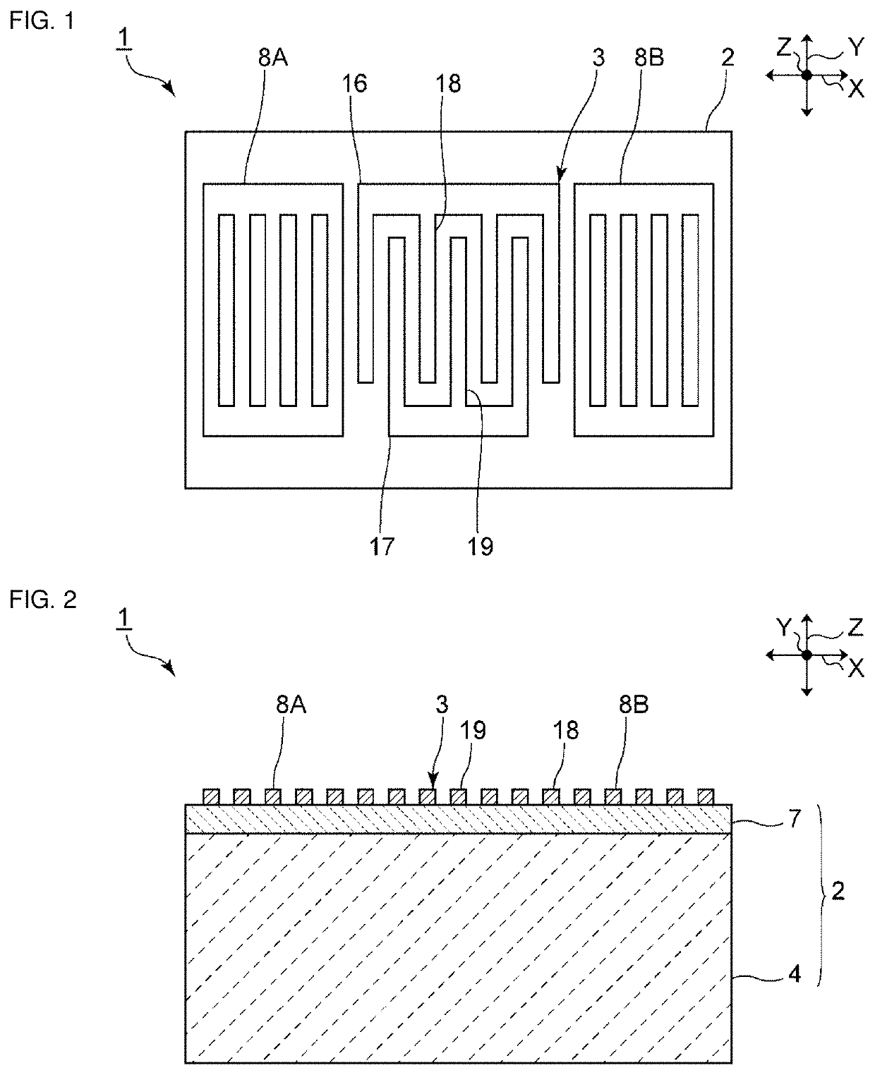
[0045]FIG. 1 is a plan view of an acoustic wave device according to a First Preferred Embodiment of the present invention.

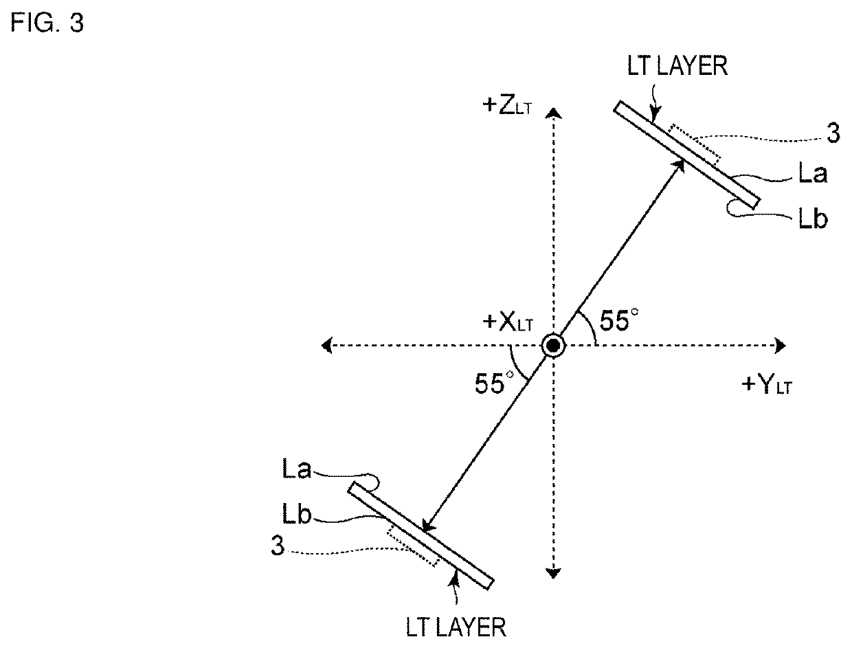
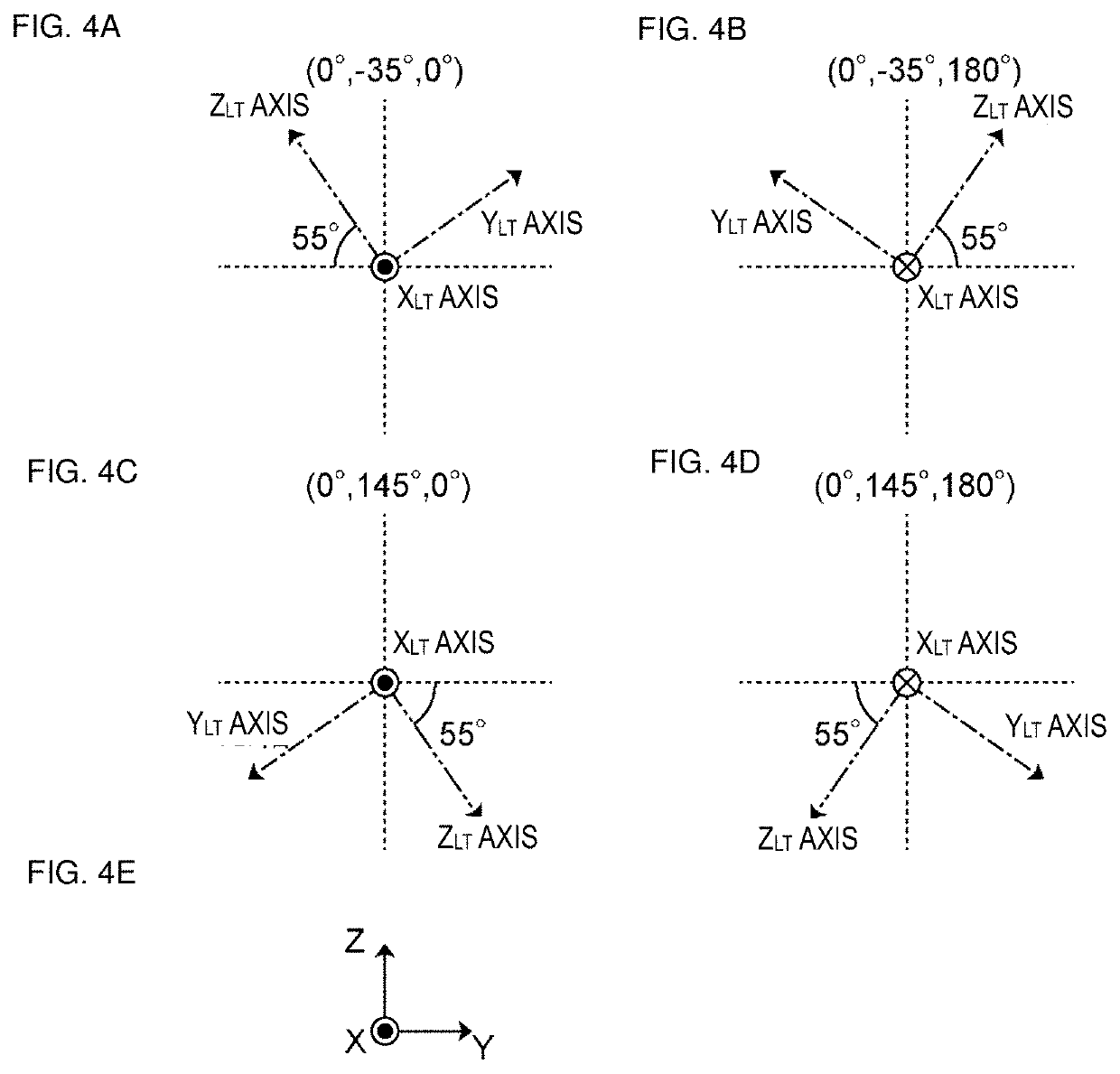
[0046]An acoustic wave device 1 includes a piezoelectric substrate 2. An IDT electrode 3 is provided on the piezoelectric substrate 2. Acoustic waves are excited by applying an alternating-current voltage to the IDT electrode 3. In the present specification, the propagation direction of surface acoustic waves (SAWs) is an X direction, a direction perpendicular or substantially perpendicular to the X direction is a Y direction, and a direction perpendicular or substantially p...


PUM


Abstract

An acoustic wave device includes a support substrate including silicon, a piezoelectric layer in which a rotated Y-cut X-propagation lithium tantalate is included, and an IDT electrode. A film thickness of the piezoelectric layer is less than or equal to about 1λ. When α111 is an angle between a directional vector k111, and a direction of silicon and n is an arbitrary integer, the angle α111 is in a range of about 0°+120°×n≤α111≤45°+120°×n or in a range of about 75°+120°×n≤α111≤120°+120°×n when the IDT electrode is on a positive surface of the piezoelectric layer and the angle α111 is in a range of about 15°+120°×n≤α111≤105°+120°×n when the IDT electrode is on the negative surface of the piezoelectric layer.

Description

CROSS REFERENCE TO RELATED APPLICATIONS[0001]This application claims the benefit of priority to Japanese Patent Application No. 2019-073692 filed on Apr. 8, 2019 and is a Continuation Application of PCT Application No. PCT / JP2020 / 015283 filed on Apr. 3, 2020. The entire contents of each application are hereby incorporated herein by reference.BACKGROUND OF THE INVENTION1. Field of the Invention[0002]The present invention relates to an acoustic wave device and a multiplexer.2. Description of the Related Art[0003]Heretofore, acoustic wave devices have been widely used in filters of mobile phone devices and so forth. International Publication No. 2017 / 209131 discloses an example of an acoustic wave device. The acoustic wave device includes a composite substrate including a piezoelectric single crystal substrate composed of lithium tantalate or the like and a silicon single crystal substrate bonded together. As the silicon single crystal substrate, an example is disclosed in which the pl...

Claims


Application Information

Patent Timeline
IPC IPC(8): H03H9/02H03H9/145H03H9/25H03H9/72
CPCH03H9/02574H03H9/02559H03H9/02637H03H9/72H03H9/145H03H9/25H03H9/02866H03H9/14541
Inventor IWAMOTO, HIDEKIMICHIGAMI, AKIRATAKAI, TSUTOMUNAKAO, TAKESHI
Owner MURATA MFG CO LTD
Why Eureka
Try Eureka